Hi DC Sound,
FSW will increase when you increase resistor value and the stability will be less.It should be 270R ~ 680R max.
Regards
MANOJ
FSW will increase when you increase resistor value and the stability will be less.It should be 270R ~ 680R max.
Regards
MANOJ
DC,
In an attempt to cure the overheating of zobel resistor the first time I power ApexD200.2 (original one). I installed a 5k trimmer for the freq oscillator, I had it set step by step (I think I managed to reach 3k). There was no noticeable temp changes on the zobel resistor and to some key components like fets, inductor fet driver etc. I do however found out that I had mistakeny placed a 473 value for the output cap, and when I changed it back to 474 and presto! Problem solved!
With Manoj changes I haven't done that yet, I'm not really so sure if changing the Fsw will make noticeable changes with the heating problem. I have yet to revert back to 474 cap and test the amp again.
Regards!
BTW Had you manage to test Manoj mod? The changes is a more recent approach using IR2110 (15v zener diode as internal clamp for VB & VS pin)
I'm also working on a new lay-out to cancel EMI problem (hopefully) on half filter butterworth (LPF) when using ferrite inductor.
Last edited:
Hi DC Sound,
FSW will increase when you increase resistor value and the stability will be less.It should be 270R ~ 680R max.
Regards
MANOJ
Hi Manoj,
what the frequency value Khz? if I use the 680ohms?
what the frequency value Khz? if I use the 680ohms?
Hi,
fsw depends MOSFET,TL081,Filter,Inverter and supply rail
Regards
MANOJ
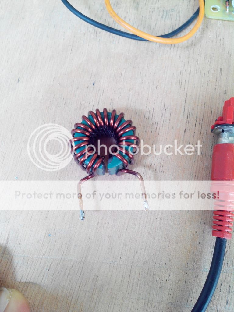
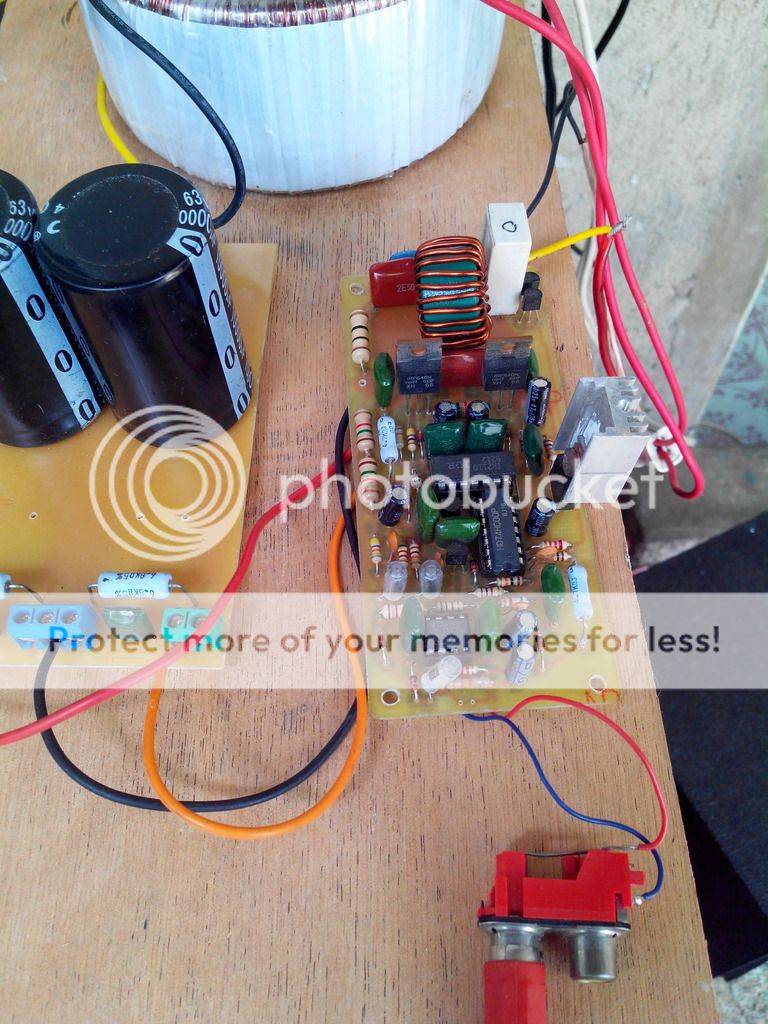
I try this green ferrite toroid from roks
On my Apex D200 and works without problem.
No overheating of output mosfet and zobel network
I put 2mm gap and wind 18 turns of #18awg magnet wire
On my Apex D200 and works without problem.
No overheating of output mosfet and zobel network
I put 2mm gap and wind 18 turns of #18awg magnet wire
I try this green ferrite toroid from roks
On my Apex D200 and works without problem.
No overheating of output mosfet and zobel network
I put 2mm gap and wind 18 turns of #18awg magnet wire
Nice work... toroid from roks????
Regards
"Roks" is a local e-parts store. The green toroid is hard to identify since it comes as surplus component.
@remle114,
how did you manage to make the cut? I had the same toroid tried to make a cut also, i used a saw file and a steel saw but It won't get through with the cut the result was a terrible scratch in the surface
@remle114,
how did you manage to make the cut? I had the same toroid tried to make a cut also, i used a saw file and a steel saw but It won't get through with the cut the result was a terrible scratch in the surface
"Roks" is a local e-parts store. The green toroid is hard to identify since it comes as surplus component.
@remle114,
how did you manage to make the cut? I had the same toroid tried to make a cut also, i used a saw file and a steel saw but It won't get through with the cut the result was a terrible scratch in the surface
Hi Abetir this is the tool i used to cut those toroid
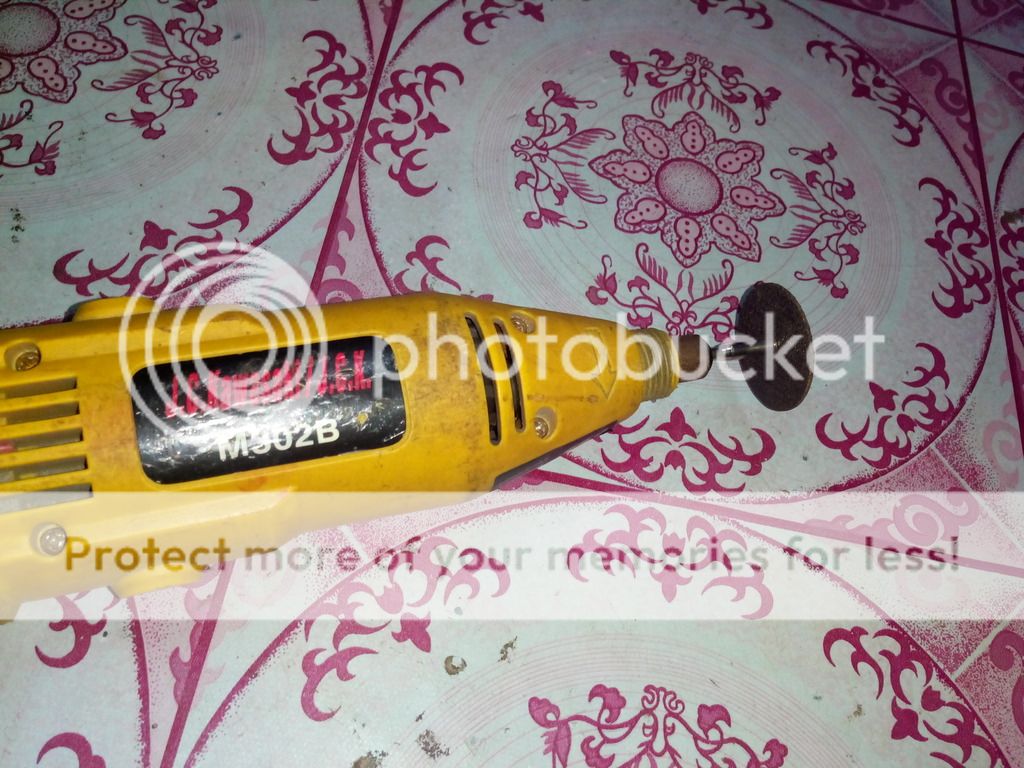
This is a Die grinder or rotary tool, very usefull for drilling PCB for cutting square hole in amplifier chasis
Last edited:
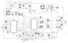
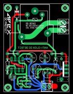
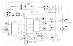
Hi Mr. Mile, is this correct? I am interested about protection circuit, could you explain it? Sorry for messy lines, first time drawing schematics with software.
Protection circuit use 0,05R with IGBT start at 25A (4000VA), use 0,1R with MOSFETs.
Protection circuit use 0,05R with IGBT start at 25A (4000VA), use 0,1R with MOSFETs.
What about changing R10 to 2k for FETs and keep 0.05R for power dissipation reasons?
What about changing R10 to 2k for FETs and keep 0.05R for power dissipation reasons?
It's ok.
- Home
- Amplifiers
- Class D
- Class D Amp with LM566, LM393 and 2XIRF530