I first assemble the power Class D but there are obstacles hoarseness can you help me, sorry I use googel translate, Greetings
thank you for all for the help for so successfully assemble Apex class D
Well, I have tested the amp with IRF640 and IRFB4227.
IRF640 and 47R gate resister worked smoothly on +/-80V supply. reducing the gate resister to 33R burnt the IRF640.
Then I tested with IRB4227 with 47/33/10R gate resisters but none of them worked even with +/- 52V supply. The amp starts like a bomb and gives me hum like booom. tuning 1K pot from 600R to 270R gave me the same result but turning it to 0R eliminated the boom sound.
used feedback setup 4.7K/56p/47K also tried with 1.2K/100p/60K. nothing could stop that.
Back to IRF640 and 47R gate resister worked fine on 8R speaker. No overheating and clear Sonics.
Wonder why IRF640 works and IRFB4227 doesn't on the same amp. I need to run it with IRF4227 +/-80v. I don't know where to look for changes to be done. Please help.
Well, I have tested the amp with IRF640 and IRFB4227.
IRF640 and 47R gate resister worked smoothly on +/-80V supply. reducing the gate resister to 33R burnt the IRF640.
Then I tested with IRB4227 with 47/33/10R gate resisters but none of them worked even with +/- 52V supply. The amp starts like a bomb and gives me hum like booom. tuning 1K pot from 600R to 270R gave me the same result but turning it to 0R eliminated the boom sound.
used feedback setup 4.7K/56p/47K also tried with 1.2K/100p/60K. nothing could stop that.
Back to IRF640 and 47R gate resister worked fine on 8R speaker. No overheating and clear Sonics.
Wonder why IRF640 works and IRFB4227 doesn't on the same amp. I need to run it with IRF4227 +/-80v. I don't know where to look for changes to be done. Please help.
how about the protection does it work perfectly??
how about the protection does it work perfectly??
Hello, Someone is listening to me 🙂
Used 2 x 0.1R/2w parallel and didn't try shorting them. But I have also tested bypassing the resisters (just grounding the output negative line) the same result.
Also I bought and tried IR2110 from different shops having different printing and batch numbers on them. So I think the issue has nothing to do with that. also changed TL081 from Texas In. to TL071 from ST. no luck!
A simple question! why is it working when FSW pot turn into 0R? then it oscillate at 225Khz.
Last edited:
hello, I test my new smps: ir2153 powered through resistance 27k 70kHz frequency that drives two IRF840 with ei33 transformer with output 2mur1560 and 2 1000uF capacitor for symmetrical voltage 57v * 2. test classed amplifier. 50w: Well, 100w: IRF840 starting to heat up. 200w: they explode! it is their maximum power or am I wrong in something
hello, I test my new smps: ir2153 powered through resistance 27k 70kHz frequency that drives two IRF840 with ei33 transformer with output 2mur1560 and 2 1000uF capacitor for symmetrical voltage 57v * 2. test classed amplifier. 50w: Well, 100w: IRF840 starting to heat up. 200w: they explode! it is their maximum power or am I wrong in something
Yes, you made a mistake. Transformers with voltage doubler rectifiers must not loaded asymmetrically, because it makes your transformer saturated. And your amplifier does this in every moment. (Not only the average must be symmetrical.) 1st step: make 2 (symmetrical) secondary, and a full bridge rectifier. Maybe other modifications will also be needed to get optimal results.
Hello, Someone is listening to me 🙂
Used 2 x 0.1R/2w parallel and didn't try shorting them. But I have also tested bypassing the resisters (just grounding the output negative line) the same result.
Also I bought and tried IR2110 from different shops having different printing and batch numbers on them. So I think the issue has nothing to do with that. also changed TL081 from Texas In. to TL071 from ST. no luck!
A simple question! why is it working when FSW pot turn into 0R? then it oscillate at 225Khz.
check and measure the voltage of the ir power supply if it is 12 vlts or sagging to 10vlts . also what is the value of your boost trap diode??
Yes, you made a mistake. Transformers with voltage doubler rectifiers must not loaded asymmetrically, because it makes your transformer saturated. And your amplifier does this in every moment. (Not only the average must be symmetrical.) 1st step: make 2 (symmetrical) secondary, and a full bridge rectifier. Maybe other modifications will also be needed to get optimal results.
you mean like the below rectification causes the former to saturate ???
Attachments
you mean like the below rectification causes the former to saturate ???
No. This is not a voltage doubler, but two single way, single phase rectifiers, and this is a fly-back PSU, not push-pull forward converter like mouhamed's circuit.
check and measure the voltage of the ir power supply if it is 12 vlts or sagging to 10vlts . also what is the value of your boost trap diode??
Thanks for the reply
It's 11.89V and the diode is MUR120
When I increase the 1K pot from 0R. it increases the power supply positive rail voltage from 52v to 80v and even to 101v, is It because of my inductor? it is 45 turns on T106-2.
I made a few changes..
65 turns on T106-2
27R gate resisters on IRFB4227 22R and 10R are not stable
supply +/-52V
removed the O/C protect
when FSW 1K trimpot set to 0R amp is stable. works at 153Khz
when it starts humming until about 600R then from 600R to 1K again stable and works at 213Khz but cant increase the volume, starts hearing cracky noise just like clipping noise. FETs also heats up quite a bit.

Hello mister Mile 🙂
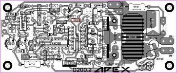
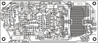
I have a simple, question, what component is this R120 it has a cathode at the end 😕 ? I'm not sure if this is a diode that I don't know maybe, see image from post #378
let me know when you get a chance = "time" 🙂
Best Regards
Juan
http://www.diyaudio.com/forums/class-d/182900-class-d-amp-lm566-lm393-2xirf530-38.html#post3382791
Attachments
Got it mister Mile clear out that too 🙂http://www.diyaudio.com//www.pinterest.com/pin/create/extension/
Attachments

I made a few changes..
65 turns on T106-2
27R gate resisters on IRFB4227 22R and 10R are not stable
supply +/-52V
removed the O/C protect
when FSW 1K trimpot set to 0R amp is stable. works at 153Khz
when it starts humming until about 600R then from 600R to 1K again stable and works at 213Khz but cant increase the volume, starts hearing cracky noise just like clipping noise. FETs also heats up quite a bit.
if his voice like this?
https://youtu.be/bdx0e6wrtho

Hi
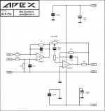
How does the second opamp work in this diagram? In which way you'll increase the volume?
Thanks in advance!
If wiper is on the right end, volume will be almost zero, on the left end gain is 2.2, and between them you will get a nonlinear position-gain function, similar to dB scale. Not really dB, but quite usable, much better then linear. I prefer gain of 5, it gives more similar result to dB scale.
- Home
- Amplifiers
- Class D
- Class D Amp with LM566, LM393 and 2XIRF530