If wiper is on the right end, volume will be almost zero, on the left end gain is 2.2, and between them you will get a nonlinear position-gain function, similar to dB scale. Not really dB, but quite usable, much better then linear. I prefer gain of 5, it gives more similar result to dB scale.
Thank you very much!

That noise can be heard without even the input signal. I think its oscillation noise of the outputs.
Also I have found several duplicate ICs in the market. They give different results. Make sure components are originals.
HI CAN I USE T106-26 CORE FOR D200-2
Please refer these pages.
Micrometals, Inc. - Power Cores
T106-2
I'm using T106-2 which works fine. but I'm not sure your material works as the output inductor. Most probably it will heat up like an iron.
Hello mister Mile
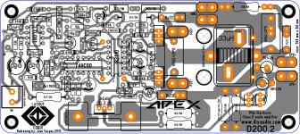
I made a re-drawing of your design the D200.2 and I just move the coil away so I can easily screw the mosfets to a main larger heat sink I think I gonna try this one later 🙂 about jumpers I place a top trace and with a bit of solder will complete the connections.
Best Regards
Juanhttp://www.diyaudio.com//www.pinterest.com/pin/create/extension/
Attachments
Last edited:
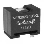
I have a question guys, is this coil can be use on the D200.2 is 33uH part number VER2923-333KL they also have 22uH 🙂
This coil can be use on D200
Regards
This coil can be use on D200
Regards
good to know that thanks mister Mile 🙂 I was thinking that I want to try out D200.2 that is why I look for an extra possibility of coils options but I also leave the first option coil a regular "O" type coil here are some images and also to leave some space for the IRF640N to screw them into a larger heat sink too 🙂
Best Regards
Juan
Attachments

Hello guys
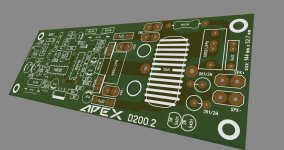
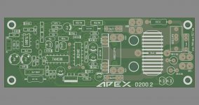
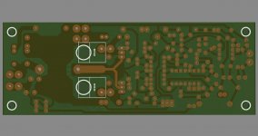
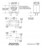
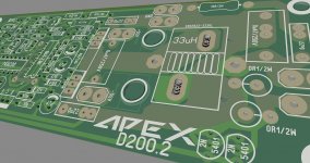
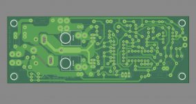
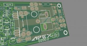
this is I think the last layout if any more options needed let me know, this is just a redrawing of the original file that mister Mile already post long time ago I think is a great project to do and I want it to learn class D from this design maybe later I will order a few PCB to try out, the only thing I want to have a more space so the mosfets can be screw them into the heat sink more easily and also I add the heat sink option so it will secure TIP31C better, also as you can see I have a bit more space on the PCB I add two 0R1 3W resistors in case you don't want to install upright way those resistors, and lastly I add a European type terminal and I leave the the original input if you want just to solder the input wire to that area, the coil I decide to leave the original dona "O" type and add the "fancy" too part number VER2923-333KL 33uH 100 amps here are an image of the coil been use, like this Class D amplifier, the PCB size is now 144 mm x 64 mm
I just put my ideas here I'm not an expert but I like to share PCB ideas 🙂
Best Regards
Juan
Attachments
Hello guys
this is I think the last layout if any more options needed let me know, this is just a redrawing of the original file that mister Mile already post long time ago I think is a great project to do and I want it to learn class D from this design maybe later I will order a few PCB to try out, the only thing I want to have a more space so the mosfets can be screw them into the heat sink more easily and also I add the heat sink option so it will secure TIP31C better, also as you can see I have a bit more space on the PCB I add two 0R1 3W resistors in case you don't want to install upright way those resistors, and lastly I add a European type terminal and I leave the the original input if you want just to solder the input wire to that area, the coil I decide to leave the original dona "O" type and add the "fancy" too part number VER2923-333KL 33uH 100 amps here are an image of the coil been use, like this Class D amplifier, the PCB size is now 144 mm x 64 mm
I just put my ideas here I'm not an expert but I like to share PCB ideas 🙂
Best Regards
Juan
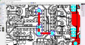
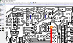
Great work! Thumbs up! I suggest you to include a 1K trimpot instead 510R FSW resister which needs to set the frequency.
Also if you need to increase the voltage up to 90+, 2W resisters could be replaced by 5Ws otherwise this is fine. and make it to use both O type and E type inductors.
Great work! Thumbs up! I suggest you to include a 1K trimpot instead 510R FSW resister which needs to set the frequency.
Also if you need to increase the voltage up to 90+, 2W resisters could be replaced by 5Ws otherwise this is fine. and make it to use both O type and E type inductors.
hello sir I made last modification today and you are the 2 second person to mention to add a trim pot to the 510 resistor I do not mind to add it for sure 😉 this is how it looks today probably tomorrow I will add the trim pot for sure I will find some space for it 🙂
Best Regards
Juanhttp://www.diyaudio.com//www.pinterest.com/pin/create/extension/
Attachments
Last edited:
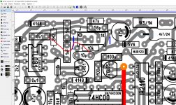
any way. I wasn't that sleepy jejejejeje I just add the trim pot 🙂http://www.diyaudio.com//www.pinterest.com/pin/create/extension/
Attachments
any way. I wasn't that sleepy jejejejeje I just add the trim pot 🙂http://www.diyaudio.com//www.pinterest.com/pin/create/extension/
Remove jumper...
Attachments
Remove jumper...
thanks for let me know mister Mile, I'm consider order a few PCB to KikiPCB later 🙂
Best Regards
Juanhttp://www.diyaudio.com//www.pinterest.com/pin/create/extension/
Attachments
Last edited:
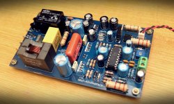
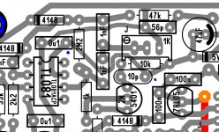
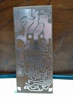
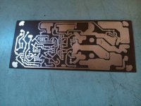
first etching of the Apex D200.2 redrawing
made by mister Equipe Décadas 🙂
http://www.diyaudio.com//www.pinterest.com/pin/create/extension/
made by mister Equipe Décadas 🙂
http://www.diyaudio.com//www.pinterest.com/pin/create/extension/
Attachments

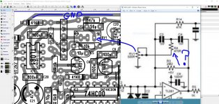
I apologize to ask too much mister Mile is there a complete schematic of the D2002.2 ?
post #717

Can you share layouts
Attachments
- Home
- Amplifiers
- Class D
- Class D Amp with LM566, LM393 and 2XIRF530