This amp is ideal for very sensitive speakers.
For the outputs, Toshiba 2SC5200 or 2SC3281 are good or use On Semi MJL4281 or the FJL4315 ( same as the 2SC5200)
Make sure you use a very good audio grade output cap (4700uF). I use an offboard cap board and use multiple caps to make up the required capacitance with film bypass caps. Elna RFS or Cerafine ROA, or Nichicon UKA, UKZ or UES.
Probably no need for a soft start module as the amp is only 4W per channel. Use a Cap mx psu card for your power supply.
Yep, I agree Gary. Using a capMx for psu has the benefit of a slow power ramp up, it’s like a built in softstart 🙂
Mine has 2SC3281 installed, I haven’t got around to upgrading the Pani FC output cap yet.
Mine has 2SC3281 installed, I haven’t got around to upgrading the Pani FC output cap yet.
I have easy access to Onsemi 2SC5200 so will probably get these along with Nichicon FG caps. Is there a BOM available for this as unsure of some of the resistor wattage values?
The output transistor resistor R5 (or R11/R12 on Prasis's schematic) is 3 watt or 5watt, all other resistors are the usual 0.25W/0.5W that will fit the pcb. Your choice of the Nichicon FG's is good for the output cap to fit the pcb.
Have fun building the amp, read up and think about biasing at 1.25Amps by changing the value of the R5 resistor to be 0.5ohms (from 0.6 ohms)
Have fun building the amp, read up and think about biasing at 1.25Amps by changing the value of the R5 resistor to be 0.5ohms (from 0.6 ohms)
Thanks for the info Gary!
I need to think about a suitable case and the Modushop Mini Dissipante looks favourite if not the cheapest option, but I'm not convinced that some of the Ali Express / Chi-Fi cases have sufficient heatsink mass. When you factor in import tax and shipping they're not a far apart as I first thought.
My main speakers are 16 ohm so might look at changing the output caps to 2200uF. More reading up required!
While I'm talking about reading up - I don't suppose anyone could recommend a good book or resource for getting a better understanding of audio circuits?
Ta
Last edited:

If anyone is interested in some PCB's made from Prasi's gerbers to build this amp, if you pay shipping they are as good as yours. Send me a PM if interested!
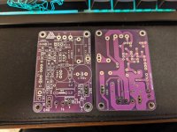
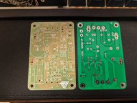
I have 14 total pairs for these boards, all are from JLCPCB, HASL-Lead Free finish. 7 of the boards are green single sided, 7 are purple double sided, I've attached some pictures.
I have 14 total pairs for these boards, all are from JLCPCB, HASL-Lead Free finish. 7 of the boards are green single sided, 7 are purple double sided, I've attached some pictures.
Attachments
PCBs now made and making their way to me on the slow boat. A few more silly questions from me I'm afraid...
Initially I'll be powering this from my bench power supply to make sure my first amp build doesn't go up in smoke. Is there any reason I shouldn't keep the power floating or should it be grounded to mains earth?
I've also decided I'd like to power this with a linear power supply and would like to miniaturise what's in my F7 but with something like a 160VA torroid - its exceptionally quiet and has little to no startup thump. Could anyone recommend any suitable boards for this?
A good idea, but what chip in your opinion can I apply here? It would be good AD8045 but it has a low power.
Attachments
I've had no luck in sourcing a single rail PCB so downloaded KiCad and had a go. I've shamelessly borrowed the old First Watt schematic from NP and butchered it a little:

that bit was easy - laying out the PCB less so. (5mm traces) This is my first attempt so no sniggering 😉

that bit was easy - laying out the PCB less so. (5mm traces) This is my first attempt so no sniggering 😉
au contraire mon frère!
Congratulations on your first attempt!
What happens if you flip both caps on the right 180º (π radians)?
Kind regards,
Drew
Congratulations on your first attempt!
What happens if you flip both caps on the right 180º (π radians)?
Kind regards,
Drew
Like this?What happens if you flip both caps on the right 180º (π radians)?
Why those negative line splits? You like for current to go back and forth when charging and discharging? I would go directly to the cap, then further from there, but i am no expert.
@IanA yes, that was the idea. I was hoping to avoid the crossovers.
I wish someone with more experience would weigh in. I am a beginner as well.
If you change the cap orientation so that all of the +ive leads are pointed to the center (where the resistors are), I think you can snake the blue trace (ground) along the right side.
Kind regards,
Drew
I wish someone with more experience would weigh in. I am a beginner as well.
If you change the cap orientation so that all of the +ive leads are pointed to the center (where the resistors are), I think you can snake the blue trace (ground) along the right side.
Kind regards,
Drew
I did my first attempt at the easyeda.com online site as I do not have kicad or other softwares 🙂
Here is a small renderer and I did print few boards to test my board and I tried to use small caps of 2200-4700/35-50v low noise and also they are cheaper than bigger sized caps. Hopefully it works, if you are interested here are the gerber files.
Note: This board is yet to be tested.

Here is a small renderer and I did print few boards to test my board and I tried to use small caps of 2200-4700/35-50v low noise and also they are cheaper than bigger sized caps. Hopefully it works, if you are interested here are the gerber files.
Note: This board is yet to be tested.
Attachments
hi, this amp is capable of driving 4ohm speaker?
I've built mine but it distorts on the high frequencies when i play some piano songs, I've set the Voltage zero to V/2 + 0.8 and i'm running the amp at 20V 1A.
What could it be?
All the values and transistor orientation are correct.
The Bc transistor were matched using Hfe.
I've built mine but it distorts on the high frequencies when i play some piano songs, I've set the Voltage zero to V/2 + 0.8 and i'm running the amp at 20V 1A.
What could it be?
All the values and transistor orientation are correct.
The Bc transistor were matched using Hfe.
- Home
- Amplifiers
- Solid State
- Class A, 4 Watt, No Feedback, Simple Circuit, Great Sound