Joe - I've just been checking these. The BD139/140 are definitely correct as I've popped some spare ones in a tester. Just need to work through the little buggers now...
And be alert. Power dissipation of some parts could be on the edge with 35VDC.
If you can simulate the circuit i would do so or drop some voltage with high power resistors in series with the board
If you can simulate the circuit i would do so or drop some voltage with high power resistors in series with the board
I've checked all the transistors with spares in the tester and the orientation is correct. I'll now check the passive components...
I'm only powering the circuit with 20V DC.
I'm only powering the circuit with 20V DC.
DC output voltage V/2+0.8 Volt so for 20V in should be 10.8 V (as per post#4) but I'm only getting 0.69V
I'll look at this tomorrow with a fresh pair of eyes.
I'll look at this tomorrow with a fresh pair of eyes.
Are you sure your bench power supply is not set to limit current?I've made some progress. Drilled and tapped the heatsink and attached to bench PSU. Unfortunately the current draw is only 20-30mA (shown on bench PSU) whatever I do with the pot and seem unable to bias the circuit.
Could anyone point me in the right direction for troubleshooting and what measurements to take? (this is my first build so patience is appreciated)
Many thanks
View attachment 1044632

Compare voltages between the 2 pcb's as you move through the circuit, you should see where the problem is doing this now you have a fully working board to compare with.
Look for a wrong value resistor, faulty transistor or a bad solder joint.
Look for a wrong value resistor, faulty transistor or a bad solder joint.
Well, no PCB here but this works for me!
Temporary setup, but the 18v lithium ion battery works well for testing...doesn't stay at 18v for long mind you!

Temporary setup, but the 18v lithium ion battery works well for testing...doesn't stay at 18v for long mind you!
My first amp project is alive - I now have a working stereo pair!
I'll be buggered if I know what was wrong with the first board. My desoldering skills are NOT yet at an acceptable level - I managed to mangle it somewhat while troubleshooting 🙁
The boards seem very well matched and draw exactly the same current which is nice. After 30 minutes the bias is very stable and running nice and cool on the Modushop mini-disapante heatsinks. This amp is very clean sounding, I can't detect any distortion whatsoever and no perceptable noise (with the bench PSU). I don't want to get too carried away but the sound is very favorable compared to my First Watt F7.
Next job is to finish off the case and connect up a permanent PSU - I have a nice toridal arriving next week.
Huge thanks to @lineup for such an elegant, simple and rather lovely sounding design, and to @prasi for kindly sharing his great boards and to everyone who has helped with their comments to assist me with my first build.
Ian
The transformer / PSU is in and everything wired up. Checked earthing with meter and everything looks safe on that front. Slightly nervous of switching on to be honest! Any last minute advice or checks to do?

Congratulations Ian!
Welcome to Class A single ended sound..... it's quite different to most PP Class AB amplifiers.
Not powerful, but intensely musical.
Hugh
Welcome to Class A single ended sound..... it's quite different to most PP Class AB amplifiers.
Not powerful, but intensely musical.
Hugh
Yes, tons of distortion added do make sound "quite different" and "Intensely Musical" to some, but not to everyone. I know what I am speaking about, my ancient 21 years old amplifier sin can be easily found on internet. Hopefully, I have not continued in such design path 😀.
https://sound-au.com/project83.htm

https://sound-au.com/project83.htm
Last edited:
Pavel, it is only a preference, regardless of august engineering principles..... like food, or cars, or clothing.
But it is very popular......
But it is very popular......
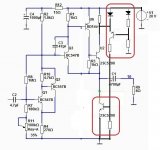
While studying the original circuit I was wondering if the current source on the output stage could be replaced with a "Taylor" circuit (as in P. L. Taylor's Audio Power Amplifier Wireless World June 1973) - the red boxed circuit.
The number and type of components used is about the same as the original circuit.
In this way the maximum "negative current" in the load is not limited to the current set by the current generator but is (much) greater.
The number and type of components used is about the same as the original circuit.
In this way the maximum "negative current" in the load is not limited to the current set by the current generator but is (much) greater.
Attachments
Last edited:
Congratulations Ian!
Welcome to Class A single ended sound..... it's quite different to most PP Class AB amplifiers.
Not powerful, but intensely musical.
Hugh
I'm not a stranger to Class A - my other amp is a FW F7 🙂
I summoned up the courage to power it up earlier today and it's utterly silent with no hiss or hum or power on thud (I have added a NTC thermistor). There is an unexpected voltage drop from my calculation (caused by NTC?) and I'm getting around 19V instead of 20V, however the bias was off only 0.2V from powering on a bench PSU.
I decided on this design for my first project as I have extremely efficient speakers (101db/W) and must only be listening in the miliwatts region.
This does sound a different beast to the First Watt. It's extremely clean sounding with plenty detail (and bass surprisingly) but something intangible seems missing. I know it's a bit of an unfair comparison, but I had high hopes of this simple circuit. I'm wondering if this has something to do with the amount of feedback? I've not amassed enough knowledge yet but is the feedback controlled by R1 and could this be adjusted without throwing the whole thing out of kilter?
Look, what you need is to measure distortion at the output at say 100mW, 1W and 10W, at 1kHz and 10kHz. This will give you some view what it is doing. Guesses and second guesses about class of operation or feedback ratio are pointless, it is nothing but audiophile bla bla. This is technology and engineering and it follows laws of physics. Nothing else, nothing mysterious.
- Home
- Amplifiers
- Solid State
- Class A, 4 Watt, No Feedback, Simple Circuit, Great Sound