With 20V and 1A bias you will only get 2W without distortion out of it so chances are you are eventually clipping it.hi, this amp is capable of driving 4ohm speaker?
You could lower R5 (0R6) to 0R4 to raise bias to ~1.5A for ~4W output and thus more headroom.
Power dissipation will rise to 30W and the output stage transistors will have 10-15W on them.
You could lower the supply voltage a little (if possible) to compensate ~18V or use CRC-filters to drop some voltage.
Thanks!With 20V and 1A bias you will only get 2W without distortion out of it so chances are you are eventually clipping it.
You could lower R5 (0R6) to 0R4 to raise bias to ~1.5A for ~4W output and thus more headroom.
Power dissipation will rise to 30W and the output stage transistors will have 10-15W on them.
You could lower the supply voltage a little (if possible) to compensate ~18V or use CRC-filters to drop some voltage.
Hi Prasi,
PCBWay rejected the gerber files because they do not have any top soldermask layer. Do you have any hint to complete this? I have submitted the LINEUP 4W AMP-OPT3_2021-11-23.zip file.
Thanks.
PCBWay rejected the gerber files because they do not have any top soldermask layer. Do you have any hint to complete this? I have submitted the LINEUP 4W AMP-OPT3_2021-11-23.zip file.
Thanks.
If anyone is interested in some PCB's made from Prasi's gerbers to build this amp, if you pay shipping they are as good as yours. Send me a PM if interested!
I have 14 total pairs for these boards, all are from JLCPCB, HASL-Lead Free finish. 7 of the boards are green single sided, 7 are purple double sided, I've attached some pictures.
I received the boards, thanks bloqhed, and build the amp. It works, but one channel overheats. Must be some simple issue, short, or wrong part. Do not have time to deal with it right now.
I know taste and each one's systems are different but im very curious what you think of the amp in comparison with Nelson's designs that you built Adason
not much comparison yet
just listening on little test bookshelf speakers
prior to this little 4watts, I was listening to my buffer in the same setup
so I can only compare these two side by side
this 4watts classA is sweet, detailed, has great top, but lacks low end authority
ideal use for this amp is tweeter or fullrange in biamp system
my buffer sounds better, with greater depth
but I am biased 🙂
Boards arrived but build ground to a halt as I missed RZ from my BOM - a rookie error 🙄

Are cheapy ceramic caps OK for the small values as they don't seem to be in any signal path?
I also need to sort out a "test" heatsink to practice tapping some M3 holes - another skill I need to learn.
If anyone in the UK fancies building this I have spare boards I can send at cost - send me a PM.
Are cheapy ceramic caps OK for the small values as they don't seem to be in any signal path?
I also need to sort out a "test" heatsink to practice tapping some M3 holes - another skill I need to learn.
If anyone in the UK fancies building this I have spare boards I can send at cost - send me a PM.
I have used the following for the caps in this design:
Rz = 0.1uF 100V film
C2 = 47pF Silver Mica
C5 = 330pF 100v film
C1 = 4.7uF PP film
C4 = 4700uF 35v audio grade electro cap. eg Nichicon UKA.
Rz = 0.1uF 100V film
C2 = 47pF Silver Mica
C5 = 330pF 100v film
C1 = 4.7uF PP film
C4 = 4700uF 35v audio grade electro cap. eg Nichicon UKA.
Thanks Gary. Is there any reason choosing the 47pf mica over a film one?
I have the 4.7u (Vishay) and 4700u (Nichicon FG) already
I have the 4.7u (Vishay) and 4700u (Nichicon FG) already

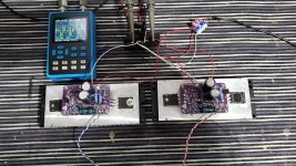
I can confirm that the boards are working fine with a test rcore transformer I checked with the 23VAC rail I get a stable 34.2vdc because of my home voltage being a bit higher than the normal 220vac. Here are some of the pics using Samwha 4700/50v caps and pair of BPR 0.33R/5W resistors.I did my first attempt at the easyeda.com online site as I do not have kicad or other softwares 🙂
Here is a small renderer and I did print few boards to test my board and I tried to use small caps of 2200-4700/35-50v low noise and also they are cheaper than bigger sized caps. Hopefully it works, if you are interested here are the gerber files.
Note: This board is yet to be tested.
I've made some progress. Drilled and tapped the heatsink and attached to bench PSU. Unfortunately the current draw is only 20-30mA (shown on bench PSU) whatever I do with the pot and seem unable to bias the circuit.
Could anyone point me in the right direction for troubleshooting and what measurements to take? (this is my first build so patience is appreciated)
Many thanks

Could anyone point me in the right direction for troubleshooting and what measurements to take? (this is my first build so patience is appreciated)
Many thanks
I've made some progress. Drilled and tapped the heatsink and attached to bench PSU. Unfortunately the current draw is only 20-30mA (shown on bench PSU) whatever I do with the pot and seem unable to bias the circuit.
Could anyone point me in the right direction for troubleshooting and what measurements to take? (this is my first build so patience is appreciated)
Many thanks
View attachment 1044632
I'm not entirely sure if it applies to your situation, but I recall in post #139 it was mentioned that the output cap can't be hanging and you need to load the speaker output by tying a 100R/2w resistor from output to ground.
I have a 12ohm 20W resistor connected to the output. I've also remembered to solder the jumper JP1. I know it's likely to be something silly but I'm at a bit of a loss...
- Home
- Amplifiers
- Solid State
- Class A, 4 Watt, No Feedback, Simple Circuit, Great Sound