Re: Re: Re: Choke loaded SOZ
Or even better a 50 mH choke
Magura
Magura said:
Is there anything gained by just replacing the r1 and r2 of the SOZ by chokes of 80 mH?
Or even better a 50 mH choke
Magura
http://madisound.com/3way.html
14.5mH, 1R13, USD$4.25
15W/8R would be 2A bias, less than 5W in the coil, 2.25V drop, 88hz is -3dB for 8R.
They have chokes of this value with lower DCR for more money, I guess the real question is how much does the inductance change at 2A DC?
As it looks, this might be good for an amplifier used with a 200hz/24dB crossover.
Re: Re: Re: Choke loaded SOZ
In general principle, particularly with bigger amps you get half sized power supply, half sized heatsinks, half sized electricity bill.
The power supply and heatsink thing can mean big $$$ saving.
What power output is SoZ? 10 watts or so?Magura said:Is there anything gained by just replacing the r1 and r2 of the SOZ by chokes of 80 mH?
In general principle, particularly with bigger amps you get half sized power supply, half sized heatsinks, half sized electricity bill.
The power supply and heatsink thing can mean big $$$ saving.
Re: Re: Re: Re: Choke loaded SOZ
A SOZ is scaleable from around 5W to 50W, though more than 25W isnt practical dur to powerconsumption (more than a regular mains outlet can handle (230V 13A)).
I just dont understand how i can replace the 8 ohm bias resistor with a 2.5 ohm inductor...something must go wrong....at least the gain must go through the roof...no???
Magura
Circlotron said:
What power output is SoZ? 10 watts or so?
In general principle, particularly with bigger amps you get half sized power supply, half sized heatsinks, half sized electricity bill.
The power supply and heatsink thing can mean big $$$ saving.
A SOZ is scaleable from around 5W to 50W, though more than 25W isnt practical dur to powerconsumption (more than a regular mains outlet can handle (230V 13A)).
I just dont understand how i can replace the 8 ohm bias resistor with a 2.5 ohm inductor...something must go wrong....at least the gain must go through the roof...no???
Magura
If the choke had zero resistance you should reduce the dc supply voltage by whatever was normally dropped across the 8 ohm resistors. With a 2.5 ohm choke it should be reduced by somewhat less. The bottom line is, no matter what the configuration, at no signal the source-drain voltage should always be the same.
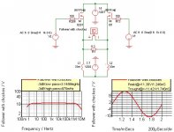
A source follower is WAY less hassle. An interesting way that Fuling suggested was to have two source followers running antiphase and the speaker connected between the sources. It is good because
1/ there is no choke voltage drop applied to the speaker.
2/ even harmonic distortion from the square-law charactistic of the mosfet is cancelled out
3/ you can use two smaller chokes.
You can't use a single centre tapped choke for this because then the two opposite direction currents make you lose the effect of the energy stored in the airgap. Well, you *could* use a single centre tapped winding with no airgap but then it becomes a transformer and the imperfect coupling between the winding halves introduces a whole new set of problems.
Try a source follower cct and see how you go. It's reeeeaaaalllly easy.
One other thing, see how well a source follower cct goes for you; it goes great for me.
BTW, did I mention to try a source follower.
New mantra - source follower.
PS. Source follower.
I suppose it would in the SoZ setup too.Circlotron said:2/ even-harmonic distortion from the square-law charactistic of the mosfet is cancelled out
I think the world needs a source-follower SoZ.
Source followers... Yep, I´m in!
I´ve spent some hours this weekend trying to get a Zenlike creature with mixed feedback to work good but I must admit that I failed. My secret ingredient here was a low voltage triode instead of the resistive network that connects drain - gate- ground.
What I essentially did was to insert a cathode follower in front of the Mosfet but instead of connecting the the plate to the positive rail I wired it to different taps on the choke to get voltage feedback.
BTW there was some current feedback too in the circuit.
I said previously that this idea failed, but it didn´t fail completely.
The problem was that I only got 1W out before clipping when the voltage feedback was connected, and when I removed it (plate directly to positive rail) I got almost 4W.
To make it short: I lost half the swing. Bad.
Quite sad I must say because except for the big loss of swing rthe circuit worked quite well, I did some measurements with different ratios of voltage and current feedback and the results was very interesing.
Bottom line: Source followers... Stable, linear, easy to work with and they require no feedback. Gain can be had somewhere else.
What is with Fulink's original idea in post 7: the choke loaded IT-coupled balanced SE tube/mosfet hybrid action?
Is it work?
Is it work?
Haven´t tried it yet. Don´t know if anyone else has before either, but I guess someone has. Wait a minute, doesn´t Pathos use that topology in their output stages?
Anyway, I will build it someday when I have the time and money to spare, right now there are are a few other projects in the pipeline.
Anyway, I will build it someday when I have the time and money to spare, right now there are are a few other projects in the pipeline.
So, would this mean that i can reduce all the 8 ohm resistors in the SOZ to the resistance of the respective choke, and lower the supply voltage to match the change of resistance??
Magura
Magura
Circlotron said:
I think the world needs a source-follower SoZ.
This is an very interesting thred this one.
I have simulated this XSOZ-Follower with chockes instead of currentsinks.
It looks verry promising in the simulator, and this is only the first shot.
Regards
Attachments
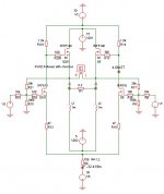
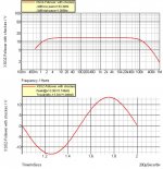
It seems as wee can get away with only 1 mH chockes besause the xfeedback "multiplys" the inductors in the closed loop, in open loop the -3db low end roll off is at 10 Hz or so.
It seems a little difficult to controll the bias, in the scematic i posted, the current is around 200 A
R101 and R14 controlles the bias current, they shoud be between 2 and 2.2 Kohm, but then unfortunately the gain gos way down, so wee are not quite there yet.
It seems a little difficult to controll the bias, in the scematic i posted, the current is around 200 A
R101 and R14 controlles the bias current, they shoud be between 2 and 2.2 Kohm, but then unfortunately the gain gos way down, so wee are not quite there yet.
I think 1mH is way too low to use in this kind of circuit.
At 20Hz the reactance is only 0,1256 ohms, so if we put a 20Hz 15V peak signal across that choke the peak current will reach 120A.
I think the minimum inductance can be calculated such that the inductive reactance (XL= 2*pi*f*L) at the lowest frequency to be reproduced is equal to or higher than the load impedance.
For 8 ohms load that would be ~60mH (30mH for 4 ohms load).
When an amp is running in balanced mode such as the SoZ or the circuit I posted in the beginning of this thread each half of the amp "sees" half the speaker load, similar to what happens when two ordinary amps are bridged.
This means that instead of using one >60mH choke for an 8 ohms load we can use two 30mH chokes instead.
As Circlotron already has pointed out there are some benefits related to balanced circuits: The possibility of direct coupling to the speaker and cancellation of second order harmonics.
I can think of one more: Constant current draw from the PSU.
Thinking of it, the PSRR must be great too.
Henrik! Using feedback to correct for an undersized inductor?
My feedback theory is make the circuit operate correctly without feedback, and then apply the minimum amount of feedback to correct for unpredicted or inherent nonlinearities.
Feedback forces the lower-order distortion by-products up. Feedback won’t eliminate the distortion – because feedback has a time constant, distortion crops up at a higher frequency. Usually this is in the upper (non-audible) band, but it creates undesirable intermodulation distortion.
To operate an amp with a 1mH choke, an enormous amount of feedback must be used to correct the frequency response. No wonder the currents were so high!
Make the amp work without feedback, and then add a bit in later to correct for the MOSFET distortion.
Exactly.
Even if the frequency response can be straightened up by using feedback, the current peaks will still be there.
What we really want between source and ground is something with zero DC resistance and infinite AC impedance, and the impedance of a 1mH choke is far from infinite.
Even if the frequency response can be straightened up by using feedback, the current peaks will still be there.
What we really want between source and ground is something with zero DC resistance and infinite AC impedance, and the impedance of a 1mH choke is far from infinite.
Chokes, anyone??
Have a look at www.hammondmfg.com
Ex:
159ZC 60mH 2A 0,7 ohm
159ZE 28mH 3A 0,43 ohm
193V 150mH 3A 1,0 ohm
195T5 100mH 5A 0,64 ohm
Remember that chokes can be wired in series or // just like resistors.
Have a look at www.hammondmfg.com
Ex:
159ZC 60mH 2A 0,7 ohm
159ZE 28mH 3A 0,43 ohm
193V 150mH 3A 1,0 ohm
195T5 100mH 5A 0,64 ohm
Remember that chokes can be wired in series or // just like resistors.
Hi all
My point is to get the best sound from an amp, not only in therory but as a practical matter, where you ears makes the final judgement. My goal isn´t to correct for an undersized inductor no matter what.
Distortions figures don´t always make me nerveous, i have worked with x-feedback for two years now, an if proberly implanted in the right circiut it really shines. The scematic i suggested includes not only feedback but also x or supersymmetry, since i have had so good realworld expieriences with xing the SOZ and BSOZ. So X-ing is my goal, and all i can say is, that you might get away with a smaller inductor with regard to the bandwith measured, not nessesarily to the sound, i agree on that one. But the question is, does the inductor need to be as large as 50mH to 1H in an X-circiut? May be may be not, i haven´t tried or heard.
I haven´t said that i have all the aswers to this amp - i have just been thinking loud - and the problem about the bias isn´t solved among others, and may be it can´t. I will give it a try later
Regards
My point is to get the best sound from an amp, not only in therory but as a practical matter, where you ears makes the final judgement. My goal isn´t to correct for an undersized inductor no matter what.
Distortions figures don´t always make me nerveous, i have worked with x-feedback for two years now, an if proberly implanted in the right circiut it really shines. The scematic i suggested includes not only feedback but also x or supersymmetry, since i have had so good realworld expieriences with xing the SOZ and BSOZ. So X-ing is my goal, and all i can say is, that you might get away with a smaller inductor with regard to the bandwith measured, not nessesarily to the sound, i agree on that one. But the question is, does the inductor need to be as large as 50mH to 1H in an X-circiut? May be may be not, i haven´t tried or heard.
Wishfull thinking.Fuling said:What we really want between source and ground is something with zero DC resistance and infinite AC impedance
I haven´t said that i have all the aswers to this amp - i have just been thinking loud - and the problem about the bias isn´t solved among others, and may be it can´t. I will give it a try later
Regards
I tend to agree with Bob Pease (National Semiconductor) that simulation programs (Spice) are a crutch and hinder learning.
Maybe if they came with a sound-effects generator, went BANG!, and emanated smoke at the right time....
No amount of feedback will change the amount of energy stored in a reactive component.
The circuit in post #51 needs energy storage in the chokes. It also needs a level shift device (coupling cap, folded cascode, interstage transformer, whatever) between the diff inputs and the outputs. Then the outputs need bias.
- Status
- Not open for further replies.
- Home
- Amplifiers
- Pass Labs
- Choke Loads for Zen/Aleph Amps