In that link , there are at least 2 pics were the gate of the gain mosfet is marked at 1.5volts to ground. How is it possible ?
Does not a mosfet require at least 3.5 volt (gate - source) in order to turn on?
Does not a mosfet require at least 3.5 volt (gate - source) in order to turn on?
Hi Stefano
Take a look at this http://www.magnatec-uk.co.uk/pdf/magnatec/BUZ900.pdf
And a happy new year.
Take a look at this http://www.magnatec-uk.co.uk/pdf/magnatec/BUZ900.pdf
And a happy new year.

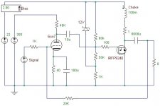
Here’s a choke-loaded follower Zen with a tube driver – no interstage transformer this time.
This circuit lets each part perform their best function: the tube is a voltage device, therefore, the tube performs voltage gain. The MOSFET is a current device, therefore, the MOSFET performs current gain.
I’ve shown some grid-stopper (or gate-stopper) resistors. There may be a few parts missing, such as a gate protection zener diode.
Now here’s the time for me to look like a real noob:
- Since the MOSFET is working in follower configuration, all of the voltage gain must be performed by the tube. How much voltage gain is needed to drive the gate? An IFRP240 has a transconductance of 6.9, so only about 2 or 3V peak-to-peak are needed at the gate? The choice of the triode will be dependant on the amount of voltage gain required.
- What’s the input impedance at the gate? A better question (showing how long it has been since I’ve worked with FETs), how is this calculated?
- The gate will probably have about 1000pF capacitance, so the driver stage should be about 1k output impedance to maintain 100kHz. Better look at those triode specs...
I’ve got everything to build this amp except for the choke. I plan on winding one this week.
Attachments
Kashmire,
I also need the inductor . Can you show up how to wind it in pratical?
I have got a pair of E83CC , can they do the a decent job in this application , or are they best employed in pre-pre cicuits such phono stage?
I also need the inductor . Can you show up how to wind it in pratical?
I have got a pair of E83CC , can they do the a decent job in this application , or are they best employed in pre-pre cicuits such phono stage?
That 1000pF is not the problem you might think. Just suppose the gate goes up by +10v and the source follows it by going up +9.8V. The gate-source voltage has only increased by 0.2v and it is *this* tiny voltage that pumps the gate-source capacitance, not the full 10v.Kashmire said:- The gate will probably have about 1000pF capacitance, so the driver stage should be about 1k output impedance to maintain 100kHz.
But wait, theres' more!
A 20v supply will pull +2.5 amps peak into 8 ohms. Therefore, bias the fet at 2.5 amps so the choke will be able to swing the speaker down to -20v as well. That shoud be ok for 25 watts into 8 ohms, in theory. The follower has a gain of 1 of course, so it needs 50v p/p drive on the gate.
A 20v supply will pull +2.5 amps peak into 8 ohms. Therefore, bias the fet at 2.5 amps so the choke will be able to swing the speaker down to -20v as well. That shoud be ok for 25 watts into 8 ohms, in theory. The follower has a gain of 1 of course, so it needs 50v p/p drive on the gate.
I would consider a 6C45Pi, plenty of drive.
http://www.audioasylum.com/forums/SET/messages/3967.html
6H30Pi
http://www.audioasylum.com/forums/bottlehead/messages/7576.html
http://www.audioasylum.com/forums/SET/messages/4550.html
WE417, 437, 5842
The bias circuit needs some work.
http://www.audioasylum.com/forums/SET/messages/3967.html
6H30Pi
http://www.audioasylum.com/forums/bottlehead/messages/7576.html
http://www.audioasylum.com/forums/SET/messages/4550.html
WE417, 437, 5842
The bias circuit needs some work.
I´d love to experiment with these circuits as well.
The tube cad article and circlotrons project look very tempting.
You can easily buy inductors up to 50mH with appropriate resistance values but they also easily cost >80€.
Anyone care to explain how much inductance is needed for certain output power. For example 10W?
TIA
Cheers
Jens
The tube cad article and circlotrons project look very tempting.
You can easily buy inductors up to 50mH with appropriate resistance values but they also easily cost >80€.
Anyone care to explain how much inductance is needed for certain output power. For example 10W?
TIA
Cheers
Jens
There are two values of interest for the choke:
(1) Inductance. This value will limit low frequency response. Large values mean lower frequency. I’ll be posting my choke design later this week. It will most likely be 33 to 50mH.
(2) DC Saturation Current. Too much static DC current will cause the magnetic field to saturate. The choke’s core must be able to handle the static current without saturation for the choke to retain it’s inductance. My design will be built to handle 2.5 to 3A of static DC current.
I looked into buying chokes.
Toroidal 120mH 2.5 Ampere power chokes will cost $45/each for 10 chokes.
Dimensions: Diameter 3.9"
Height 2.0"
Weight 2.8 lbs
Not bad ... If I order 10, does anyone want some?
Toroidal 120mH 2.5 Ampere power chokes will cost $45/each for 10 chokes.
Dimensions: Diameter 3.9"
Height 2.0"
Weight 2.8 lbs
Not bad ... If I order 10, does anyone want some?
OK. 'nuff of that simulator stuff.
Here's something I put together and debugged on Friday, that would be ok for driving a pair of source followers. You can feed just one side only and use it as a phase splitter as well, or drive it in balanced mode as per the drawing. In balanced mode it clips absolutely symmetrically. This thing has an enormous amount of gain that is ploughed right back into making the thing linear. One thing to note - the output impedance is very high and so the 1k resistors across the top choke half-primaries set the stage gain. Leave them out and the gain heads toward infinity!
The DC voltages are measured at no signal. The +62v is sort of arbitrary - it was as high as my bench supply would go. One thing is certain though, you can just wire it up and apply the voltages and away it will go. The total dissipation is about 12 watts (!) so the fets and the two voltage regs under them will need a small heatsink.
The AC voltages are measured with 2.905VAC RMS input signal just to give a general picture of the internal gain of the amp. Above this level, the output is still *extremely* linear but the mosfets start to get a little bit lazy so their sources get driven a lot harder to maintain the nice output signal. The signal is very civilised as it pulls out of clipping too.
As can be seen, the maximum output voltage is 74.66 V drain to drain. Enough to drive most things. Well, there it is.
Attachments

Circlotron: I envy your ability to produce a never ending stream of interesting circuits!
Kashmire: Torodial chokes, you say? Can the handle the DC bias?
I doubt so, since they usually don´t have airgaps
Kashmire: Torodial chokes, you say? Can the handle the DC bias?
I doubt so, since they usually don´t have airgaps
Kashmire, I certainly would be interested in a group buy but the shipping costs would probably be too high to be worth.
2.5A chokes? Wouldn´t that be too low in terms of saturating?
Anybody experienced how low you can go with the choke in terms of inductance.
I don´t trust my simulator.
With 33mH and a single ended follower an output of +20W still looks too good to be true.
2.5A chokes? Wouldn´t that be too low in terms of saturating?
Anybody experienced how low you can go with the choke in terms of inductance.
I don´t trust my simulator.
With 33mH and a single ended follower an output of +20W still looks too good to be true.
Just like a filter capacitor not needing to be a larger value for a higher power amplifier, the choke stays the same value.
The only reason to change the value of the reactive components is if you want a different 3dB down point or change the load impedance.
In the case of the capacitor the power stored is a function of the square of the voltage stored, in the case of the inductor it is the square of the current.
80mH is good for a 3dB down point of 16hz with an 8 ohm load, doesn't matter whether it is 5W or 500W.
Unless specified otherwise assume that the inductance drops 20% at the rated DC current, or the 3dB down point raises to 20hz in the above example.
Always ask the temperature rise at rated current, it may be too hot for you. The manufacture may assume a Delta of 60*C is OK unless you tell him otherwise. This would be above the boiling point of water in a 55*C ambient (glass fronted rack shelf). In this application a Delta of 30*C might be more appropriate.
The Delta is proportional to the square of the current: so if the Delta is 60*C at 4A, then it will be 2.8A at 30*C.
The manufaturer assumes:
this is a power supply
you probably have a fan
you know what you are doing
(its not his problem if you don't)
So be sure and ask if you don't know.
Yes, these chokes are rated 2.5A continuous current. They are specifically built for filtering DC power supplies.
I can also order 60mH / 5A chokes for the same price. To keep the same magnetic field on a similar core, I suppose a 96mH / 3.5A (ratiometric calculation) is also possible for the same price. These are from a magnetic core manufacturer.
As djk pointed out, 80mH is good enough for low-frequency response. A larger choke will give a little headroom because DIY projects aren’t always exact, and the load isn’t always 8 Ohms.
I’ve got my amplifier simulated in B2Spice. I’ll be posting a simulation and schematic soon. I expect to build the amp when I get some coils. Hopefully, I’ll order some this week.
If anyone is interested in buying some of my extras, the shipping costs won’t be too bad. Each choke weighs only 2.8 lbs.
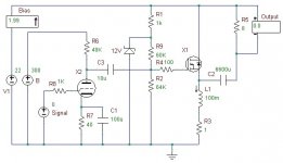
Here’s a choke-loaded source follower n-channel MOSFET amp.
This particular design focuses on using the best attributes of each active component. The MOSFET’s best attribute is controlling current, and the tube’s best attribute is controlling voltage. In addition, local feedback is maximized.
Therefore, the MOSFET is configured in source follower, which does not have any voltage gain. In this mode, the gate drive is severe (the gate voltage must be equal to output voltage), but the effect of gate capacitance is greatly reduced. All of the MOSFET’s transconductance is used in local feedback, which results in the unity gain.
The MOSFET is loaded with a choke, resulting in relatively high operating efficiency and allowing for power supplies down to 20V. The gate is tuned for 2A bias current. A zener diode stabilizes the gate bias, keeping the bias current immune to power supply variations. No filtering capacitors are shown, but the zener should be heavily filtered. Other required components not shown include a gate protection diode to protect against spikes over +20V at the gate. (Note: this circuit may also need a DC servo loop to further stabilize the gate bias)
The tube is employed for voltage gain. This simulation uses the 6sn7 using a 40k plate resistor at 300 volts (my prototype will use the 6c45pi). The triode tube uses the purest form of local feedback, the plate feedback, which is part of the natural operation of the tube.
This stage has a gain of 10, when combined with the unity-gain MOSFET output stage, 1 volt of signal will result in 10 volts of output.
Attachments
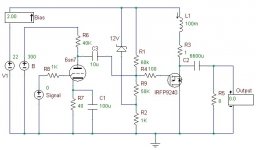
I’m a bit unhappy with the n-channel amplifier shown in the previous post. The load is attached across the active device (the MOSFET), which means the load is referenced to the positive power supply rail. I’d prefer the load to be referenced to ground.
Therefore, a p-channel design. Note the gate stabilizing zener is now referenced to the positive power supply rail instead of ground. Why is referencing to ground so magical? Read on …
Time to break the mental barrier: Nelson demonstrated some interesting attributes of a certain p-channel MOSFET in his latest audioXpress article. Is there a reason why a p-channel amp can’t sound as good as a n-channel amp, or is everyone just locked into thinking n-channels are the only way to go?
Attachments
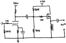
This is why ground-referencing the load was so interesting: A global feedback loop has been added. This particular schematic uses a 1k input resistor and a 20k feedback resistor. The amplifier loses some gain (1 volt input results in 8 volts output instead of 10 volts output) but distortion is reduced.
Some things are missing in the simulation that I would use in “real life”: a small capacitor (pF) across the feedback resistor to trim high frequency response, heavy filtering of the gate bias zener diode, and an active current source for the tube instead of the 40k plate resistor. I haven’t shown the power supply, either. Also not shown is a DC servo loop to further stabilize the MOSFET gain bias.
I'll update the simulation with the 6c45pi model later. The 6sn7 should be beefy enough to drive just about any MOSFET in source follower configuration, but the 6c45pi is a more powerful driver with higher gain. With the 6c45pi, this amp will be very easy to drive, and the extra gain (30) can be used to experiment with feedback.
So do you actually know what feedback sound like? Build this amp and find out. The feedback can be adjusted from gross (5k feedback resistor) to negligible (1M feedback resistor). At the end of the day, I can tell you what feedback “sounds like.” I’ll report when I get my chokes …
Attachments
- Status
- Not open for further replies.
- Home
- Amplifiers
- Pass Labs
- Choke Loads for Zen/Aleph Amps