Fuling said:
Yeah, postage...
Maybe it would be cheaper to pick them up yourself??😀
BTW, you can also get custom wound transformers and chokes from Svebry and they don´t charge much for the work.
Well, the postage prob seems to have solved itself....since if a SOZ cant be made using chokes, i wont need any....
If i ever would need a trafo from sweeden, the only way to get it here cheaper than it could be made here....would be to swim to sweeden to pick it up.....we have a few comps in DK that winds custom trafos as well, without charging an arm and a leg (if you know the right people that is) 🙂
Magura
Yes, I lost a female dog on a post I madeFuling said:Wow, I got censored
 Seems to be automatic.
BTW: Interesting thread 🙂
I really like the source-follower idea. I agree if the voltage gain can be provided elsewhere, then a choke-loaded source follower would work well.
Chokes:
About acquiring chokes: transformer manufactures are plenty. Many of them will provide you with the E-core and bobbin, letting you wrap your own. With a oscilloscope and some patience, you can assemble the iron bar across the E-core to achieve the right magnetic density. I’ve used thin pieces of cardboard or paper to fine-tune the airgap. The exact same core and windings can either be high inductance and low DC bias or low inductance and high bias, depending on how much distance is between the iron bar and the E-core.
Summary: many transformer manufactures can give you the materials to make an easy custom choke.
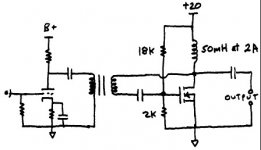
I like the schematic. 50mH may be enough for full-range sound. If you operate a tri- or bi-amped system, the midrange and tweeter amps could use 50mH or less. The woofer or subwoofer amp could be push-pull. These amps can be custom-designed for systems. I run a tri-amp dipole system with good effieincy. A good 10-watt amp is enough for the midrange and tweeter, which is why I’m looking at the choke idea.
Chokes:
About acquiring chokes: transformer manufactures are plenty. Many of them will provide you with the E-core and bobbin, letting you wrap your own. With a oscilloscope and some patience, you can assemble the iron bar across the E-core to achieve the right magnetic density. I’ve used thin pieces of cardboard or paper to fine-tune the airgap. The exact same core and windings can either be high inductance and low DC bias or low inductance and high bias, depending on how much distance is between the iron bar and the E-core.
Summary: many transformer manufactures can give you the materials to make an easy custom choke.
I like the schematic. 50mH may be enough for full-range sound. If you operate a tri- or bi-amped system, the midrange and tweeter amps could use 50mH or less. The woofer or subwoofer amp could be push-pull. These amps can be custom-designed for systems. I run a tri-amp dipole system with good effieincy. A good 10-watt amp is enough for the midrange and tweeter, which is why I’m looking at the choke idea.
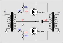
Fuling – is this the amp your were envisioning? The image is from John Broskie’s web site (http://tubecad.com/index_files/page0021.htm).
I thought about it, but I’ve been working on a different push-pull strategy seen on this thread:
http://www.diyaudio.com/forums/showthread.php?s=&threadid=24744
Thanks for the ideas, keep ‘em coming …
I thought about it, but I’ve been working on a different push-pull strategy seen on this thread:
http://www.diyaudio.com/forums/showthread.php?s=&threadid=24744
Thanks for the ideas, keep ‘em coming …
Attachments
dhaen: There must be someone on this forum who eats female dogs, I just lost one too😀
Kashmire: Biamped dipoles, interesting! That´s how my system is going to be as soon as everything gets in place. At least I hope so...
I believe the schematic I posted is more similar to pic no. 2 on John Broskie´s site, the buffer version.
I´d rather use tubes and stepdown transformers than a 1:20 stepup at the input, though.
I just read something interesting at John Broskie´s site:
"This amplifier, unlike the previous MOSFET amplifiers, must be run in strict class-A, so the idle current will be quite high, at half of the peak current demand. How do we find the peak current demand? This amplifier is effectively the equivalent to a normal source follower amplifier with +/- voltage rails twice that of this amplifier’s single rail; the magic of inductors. In this case, we can assume that 12 of the power supply’s 15 volts will be deliverable into an 8W load, so 24 volts of peak voltage would require 3A of peak current (as one terminal goes up the other goes down). Thus, an idle current of 3A is needed (24V / 8W), 1.5A per MOSFET."
This seems to indicate the difference between push pull and balanced SE operation: Since I´m going to use separate , airgapped chokes for each "leg" of the amplifier I´ll need twice the bias current, 3A per mosfet instead of 1,5A if a centertapped choke is used.
Do I make any sense here? Maybe I should wind myself a pair of CT chokes... But on the other hand, I love SE amps
Here’s a schematic … I have some 5965 and 7788 tubes here with an LL1660S/18mA interstage transformer. I’m planning on building a tube amp with these parts in March. I don’t have my output transformer yet, so these things are laying around unused …
Don’t focus on the driver stage. I’ll probably use a pentode (in triode mode) for gain around 40 and low plate impedance. These schematic I attached here shows the driver in parafeed, but I’d probably use the LL1660S interstage as single-ended running at 15mA.
Knowing that the driver will have some voltage gain, the MOSFET can run as source follower. Using a 50 mH choke with 2A bias current, this amp can run as low frequency as most good speakers – especially transmission lines and/or folded horns. I probably wouldn’t use +20V. That may be a bit high.
Don’t pick on the 18k and 2k resistors. I only used those for an example. The actual values would depend on the MOSFET and the desired bias current.
The output capacitor will probably bug some people. Nelson Pass doesn’t seem to mind too much. His Jan 2004 article explicitly says to worry about the transistor before worrying about passive components.
It’s easy enough to get rid of the output capacitor. My next post will include a schematic.
Attachments
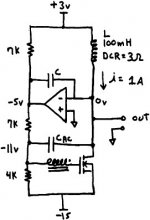
Here’s the transformer-coupled source-follower single-ended tube hybrid MOSFET amp with a DC servo loop to eliminate offset at the output.
I didn’t draw the tube drive stage. Refer to the tube forum or previous posts on this thread to see tube drivers.
Here’s how this circuit works: the op-amp is the servo loop that keeps the inverting (-) input at ground potential (by referencing ground at the non-inverting input). It does this by modulating its output to change the MOSFET’s bias. In this case, if the op-amp maintains about -5V, the bias at the MOSFET gate is -11V, or +4V from gate to source. Actual voltages and resistor values would depend on the MOSFET’s characteristics.
The bias current flows through the DCR of the choke, which causes a voltage drop. If the DCR is 3 Ohms, then a +3V power supply is needed. If the power supply voltages change a little, then the bias current changes to maintain 0V at the output.
In summary: the op-amp controls the MOSFET's bias current so that exactly the right amount of voltage is dropped over the DCR of the choke to maintain 0 volts at the output. This means (worst case) that a DC offset could occur at the output for 1 second.
The slew-rate of the servo loop is managed by C, which should be sized below the lowest frequency of the amplifier. In this case, 1Hz would work.
The signal is applied by an interstage transformer connected directly to the gate (no gate-stopper resistor is shown). The amp is configured as source-follower by the AC coupling capacitor Cac. This capacitor couples the interstage transformer to the drain of the MOSFET, making it operate in source-follower mode.
So how does the amp deliver the positive half of a waveform? As the MOSFET cuts the current off, the choke reacts and releases its stored magnetic energy in the form of positive current, resulting in positive voltage at the output. Here’s where the frequency limitation comes in: if the choke is too small, it doesn’t have enough stored magnetic energy to create a low-frequency waveform. The lower the frequency, the more stored energy in the choke’s magnetic field you need.
This amp may not be practical to build, due to the crazy +3 volt power supply requirement, but certainly feasible in theory. If you wind your own power supply transformers (or you use switching power supplies), this amp is very feasible.
Attachments
Looks good, but I can´t qute figure out how it´s going to function as a source follower. Looks more like a Zen to me.
Does it have anything to do with the fact that the input is connected between drain and gate instead of gate and ground?
Does it have anything to do with the fact that the input is connected between drain and gate instead of gate and ground?
An observation...
The problem with "losing" any cap by providing bias, is that it' hasn't been lost at all. It's just been moved fron the signal line path to the signal return path (PSU).
No critisism intended 🙂 Great ideas coming out here.
The problem with "losing" any cap by providing bias, is that it' hasn't been lost at all. It's just been moved fron the signal line path to the signal return path (PSU).
No critisism intended 🙂 Great ideas coming out here.
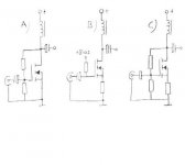
If we go back to where we started
Pretend that we leave balanced SE and PP aside for a while and look at some basic SE designs.
Drawing A shows a "regular" choke loaded Zen design that has ~twice the efficiency of a CCS loaded design. Interesting.
The big drawback is that the PSU has to be well regulated if we want to keep the bias reasonably stable. Temperature drift might be a *female dog* too.
Drawing B should be quite insensitive to PSU variations thanks to the resistor from source to ground. The problem is that this resistor introduces us to current feedback and the high output impedance which is related.
The voltage gain here would be
Rload / Rsource, which tells us that the voltage gain depends on the speaker impedance.
Might work good with some speakers (open baffles?).
Drawing C has what I think can be called mixed feedback, we have both voltage and current feedback. With the right combination of resistor values we should be able to achieve a quite high but well defined output impedance and still keep bias and temp drift under control.
This might be an attractive solution for certain speakers, I´m thinking dipoles again.
Attachments
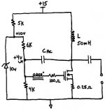
Choke loaded SOZ
Fuling! Magura!
I don't understand why can not use chokes for SOZ without to need negativ feedback for the circuit?
In the: Pass Son of Zen w/current sources (etc.) theread GRollins and Mr. Pass wrote it is possible:
"Yes, inductors would work fine. The single-ended tube folks do it all the time. It works even better without the resistor--simply replace R1&2 with really <i>big</i> inductors. The reason I haven't pursued it is that you can't just walk out and buy large value, high current inductors, and for some reason most people seem reluctant to wind their own, judging from the threads on the topic here."
"The inductance will determine the frequency response. It's a simple filter. A smaller value inductor will give you high frequencies only--perhaps good for a tweeter amplifier in a biamp system. The larger the inductor, the lower the frquencies the amplifier will reproduce. Kind of a built-in active crossover. Unfortunately, the amplifier is still trying to reproduce the lower frequencies, so you lose the benefit of less strain on the amp. Still, it will work quite nicely if you want to follow that path.
To keep track of the idea, remember two things: 1) the larger the load on a gain device, the more gain (other factors being equal), and 2) an inductor is, in a sense, a frequency dependent resistor. At DC (in other words a really, really low frequency...F=0), an inductor is close to a dead short, limited only by the resistance of the wire itself. As the frequency climbs, the impedance increases and with it, the gain. More inductance will lower the frequency at which the gain starts to climb. No inductor at all, i.e. connecting the Drains of the MOSFETs directly to the rail, will not hurt anything (as long as you don't exceed the limits of the devices) but will produce no gain.
An air core coil is a good idea because air doesn't saturate when the magnetic field gets strong. Iron core inductors are smaller but the price you pay is in performance.
A 1 Henry air core coil is a pretty large coil in every sense of the word. Hint: It'll be cheaper if you wind your own.
Go for it."
I would like to build one SOZ amp with chokes and I would use inductors made with torroid core ca 1 H, but I don't know how big resistance I need. May be 7-9 R? So I would get a "very inductiv wire wounded power resistor" 🙂
Well, my question is how can I calculate the rail voltage and transformer VA rating for a Choke loaded SOZ???
Thanks!
Fuling! Magura!
BTW with chokes instead of resistors in the SOZ the gain probably goes way up so some kind of negative feedback might be necessary. Not attractive.
I don't understand why can not use chokes for SOZ without to need negativ feedback for the circuit?
In the: Pass Son of Zen w/current sources (etc.) theread GRollins and Mr. Pass wrote it is possible:
"Yes, inductors would work fine. The single-ended tube folks do it all the time. It works even better without the resistor--simply replace R1&2 with really <i>big</i> inductors. The reason I haven't pursued it is that you can't just walk out and buy large value, high current inductors, and for some reason most people seem reluctant to wind their own, judging from the threads on the topic here."
"The inductance will determine the frequency response. It's a simple filter. A smaller value inductor will give you high frequencies only--perhaps good for a tweeter amplifier in a biamp system. The larger the inductor, the lower the frquencies the amplifier will reproduce. Kind of a built-in active crossover. Unfortunately, the amplifier is still trying to reproduce the lower frequencies, so you lose the benefit of less strain on the amp. Still, it will work quite nicely if you want to follow that path.
To keep track of the idea, remember two things: 1) the larger the load on a gain device, the more gain (other factors being equal), and 2) an inductor is, in a sense, a frequency dependent resistor. At DC (in other words a really, really low frequency...F=0), an inductor is close to a dead short, limited only by the resistance of the wire itself. As the frequency climbs, the impedance increases and with it, the gain. More inductance will lower the frequency at which the gain starts to climb. No inductor at all, i.e. connecting the Drains of the MOSFETs directly to the rail, will not hurt anything (as long as you don't exceed the limits of the devices) but will produce no gain.
An air core coil is a good idea because air doesn't saturate when the magnetic field gets strong. Iron core inductors are smaller but the price you pay is in performance.
A 1 Henry air core coil is a pretty large coil in every sense of the word. Hint: It'll be cheaper if you wind your own.
Go for it."
I would like to build one SOZ amp with chokes and I would use inductors made with torroid core ca 1 H, but I don't know how big resistance I need. May be 7-9 R? So I would get a "very inductiv wire wounded power resistor" 🙂
Well, my question is how can I calculate the rail voltage and transformer VA rating for a Choke loaded SOZ???
Thanks!
True, most amplifiers have capacitors in the output path – the PSU capacitors. For example, in a class AB amplifier, the AC component has to come from and go somewhere. That’s why big PSU caps are useful. They store energy in the capacitors can be delivered to the output.
However, with some class A amplifiers – such as the Zen – the PSU capacitors don’t play a part. The AC component of the output is a modulation of a steady-state current. Therefore, the power supply delivers steady-state and doesn’t see any AC component.
Indeed, the schematic I posted involves the PSU capacitors in the output path. The output is referenced to ground, which means the signal has to find its way to the +3V and -15V rails, which will be through the PSU capacitors.
I happen to like output coupling capacitors or transformers. I’ve blown too many direct-coupled tweeters with amps with DC offsets. That’s why the Zen amp appeals to my as a tweeter amp. Only my tube amp offers the same appeal.
Re: Choke loaded SOZ
In the beginning of the thread we all agreed to the number of 50mH as being adequate, i dont see why we should not stick to that...??
If you wind an inductor with an internal resistance of 7-9 ohm you are back where we started....or not??
But just in case you wind an inductor with 8 ohm resistance, the rail voltage and so on would be the same as for a regular SOZ.
I can get magnet wire for approx. 10 usd (65 DKK) a kilogram, give and take a bit according to dia. , so winding a few air core chokes would be no big deal and not particulary expensive (got the right equipment for winding...usually used for windings for electro motors).
If anybody is interested i can find out how much it would cost to make a few 50 mH air core chokes, able to carry 200W.
Magura
Tyimo said:Fuling! Magura!
An air core coil is a good idea because air doesn't saturate when the magnetic field gets strong. Iron core inductors are smaller but the price you pay is in performance.
A 1 Henry air core coil is a pretty large coil in every sense of the word. Hint: It'll be cheaper if you wind your own.
Go for it."
I don't know how big resistance I need. May be 7-9 R? So I would get a "very inductiv wire wounded power resistor" 🙂
Well, my question is how can I calculate the rail voltage and transformer VA rating for a Choke loaded SOZ???
Thanks!
In the beginning of the thread we all agreed to the number of 50mH as being adequate, i dont see why we should not stick to that...??
If you wind an inductor with an internal resistance of 7-9 ohm you are back where we started....or not??
But just in case you wind an inductor with 8 ohm resistance, the rail voltage and so on would be the same as for a regular SOZ.
I can get magnet wire for approx. 10 usd (65 DKK) a kilogram, give and take a bit according to dia. , so winding a few air core chokes would be no big deal and not particulary expensive (got the right equipment for winding...usually used for windings for electro motors).
If anybody is interested i can find out how much it would cost to make a few 50 mH air core chokes, able to carry 200W.
Magura
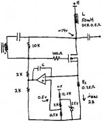
Here’s a choke-loaded source-follower Zen with some stabilized bias.
The zener diode (buffered by the 5k resistor) establishes a stable +10V reference across the bias resistor network for a stable Vgs. Since zeners are well-known sources of noise, the zener should be buffered with some caps - maybe even a little choke! (o.k. I'm getting out of hand. Where's Circ when you need 'em?)
Since we’re trying to control bias current, not gate voltage, a better way would be creating a stable reference for current. A DC servo loop could be used to control bias current using a reference. Just as a conversation piece, I’ll cook one up.
The signal is applied to the gate (through a gate-stopper resistor) with the secondary of the interstage transformer. The signal path is completed to the drain by the coupling capacitor Cac. The capacitor also serves as the local MOSFET drain-to-gate feedback path. This is very similar to the feedback of a triode-connected pentode (vacuum tubes). The feedback consumes all of the available gain, so the transistor operates with unity gain.
This forces more demands on the driver stage, which should produce a gain of about 15.
This is similar to my discussion on the push-pull thread: http://www.diyaudio.com/forums/showthread.php?s=&threadid=24744&perpage=15&pagenumber=2
Additional feedback is provided by a source resistor (0.25 Ohms in this example). An added bonus is increased stability.
I’ll be running some SPICE simulations of these circuits over the next few days. If someone beats me to it, post your results! Simulations should solve the 50mH vs. 1H debate, too.
Attachments
OK, this is my last post for now. Here’s the choke-loaded source-follower Zen with DC servo bias current control.
The op-amp compares a 0.5V stable reference on the noninverting input (+) with the voltage across the source resistor Rs at the inverting input (-).
At 2A bias current, 0.5V will form across Rs. The op-amp controls the voltage on the bias resistor voltage divider, forcing the MOSFET to maintain 2A.
The 0.5V stable reference is created using a 2.5V zener and a voltage divider. Of course, the zener should be buffered by some filtering capacitors.
Since the op-amp has to work at very low voltages, a negative power supply for the op-amp may be needed. One or two volts would be enough.
Attachments
I´m glad to see that this thread is still active!
Unfortunately I don´t have time to look closer at the drawings and interfere with the discussions right now, ´cause tonight I have some prototype breadboarding to do.
The topology will be something like drawing C in the last picture I posted, but the resistive voltage divider for the voltage feedback will be replaced by... something else😀
I´ll report tomorrow or as soon as I have anything to report.
Choke loaded SOZ
O.K. My original plan was to use a torroid core inductor for the choke loaded SOZ ,becouse I read somewhere that it will not or not so much saturate when the magnetic field gets strong like the classic Iron core inductors. So I would get very low resistance ca.2 Ohm. If I would use an 1H air core, than I would get with 16 gauge wire 5.2 Ohm or with 18 gauge 7.6 Ohm, but both can handle over 300W and I would get the "super inductive power resistor" with much heat like in the original circuit.
I am not sure the 50mH would be enough for a "fullrange amp". Mr. Pass built one also with 1 H load using a full roll of 16 gauge MWS magnet wire. ( with high resistance like a power resistor, but 40 -50 % efficiency)
"tube amps usually use about 100mA, and chokes are relatively easy to make for lower currents. The Zen amps use an order of magnitude more current, which means the chokes have to be that much larger. Pass Labs probably selected not to use chokes because it may be financially and commercially infeasible."
My questions about choke loaded SOZ:
-Should I use the inductors instead of the all power resistors from 1 to 6 or only of the 1-2? (numbers are from the original article )
-Need I make the 1 H inductor resistance as low as possible or it is not important.
-Should I use torroid core inductor?
-How can I calculate the bias and the needed PSU ratings, heat sinking?
Thanks
In the beginning of the thread we all agreed to the number of 50mH as being adequate, i dont see why we should not stick to that...??
O.K. My original plan was to use a torroid core inductor for the choke loaded SOZ ,becouse I read somewhere that it will not or not so much saturate when the magnetic field gets strong like the classic Iron core inductors. So I would get very low resistance ca.2 Ohm. If I would use an 1H air core, than I would get with 16 gauge wire 5.2 Ohm or with 18 gauge 7.6 Ohm, but both can handle over 300W and I would get the "super inductive power resistor" with much heat like in the original circuit.
I am not sure the 50mH would be enough for a "fullrange amp". Mr. Pass built one also with 1 H load using a full roll of 16 gauge MWS magnet wire. ( with high resistance like a power resistor, but 40 -50 % efficiency)
"tube amps usually use about 100mA, and chokes are relatively easy to make for lower currents. The Zen amps use an order of magnitude more current, which means the chokes have to be that much larger. Pass Labs probably selected not to use chokes because it may be financially and commercially infeasible."
My questions about choke loaded SOZ:
-Should I use the inductors instead of the all power resistors from 1 to 6 or only of the 1-2? (numbers are from the original article )
-Need I make the 1 H inductor resistance as low as possible or it is not important.
-Should I use torroid core inductor?
-How can I calculate the bias and the needed PSU ratings, heat sinking?
Thanks
Re: Choke loaded SOZ
Have a closer look at mine with the choke in the source lead. The 325 mV @ 3.5 amps across it is also used for current servo sensing. It is very very tame.
/Circlotron - reading every line in the post, but has to bite his tongue to stop butting in too much.
The 80mH ones on mine are just fine. If you want to avoid an output coupling cap, if the choke dc voltage drop is less than ~300mV or so then just wire the speaker right across it.Tyimo said:I am not sure the 50mH would be enough for a "fullrange amp".
Have a closer look at mine with the choke in the source lead. The 325 mV @ 3.5 amps across it is also used for current servo sensing. It is very very tame.
/Circlotron - reading every line in the post, but has to bite his tongue to stop butting in too much.
Re: Re: Choke loaded SOZ
Hmm...maybe its just me, but id prefer loads of "butting in", since this thread have changed from "travelling to a destination" to a sightseeing 🙂
We see a lot, but get nowhere.
Is there anything gained by just replacing the r1 and r2 of the SOZ by chokes of 80 mH?
How big would the resistance of the choke have to be?
If down to 80 mH, i see no reason to make EI chokes, an 200W air choke isnt that big.
Magura
Circlotron said:
/Circlotron - reading every line in the post, but has to bite his tongue to stop butting in too much.
Hmm...maybe its just me, but id prefer loads of "butting in", since this thread have changed from "travelling to a destination" to a sightseeing 🙂
We see a lot, but get nowhere.
Is there anything gained by just replacing the r1 and r2 of the SOZ by chokes of 80 mH?
How big would the resistance of the choke have to be?
If down to 80 mH, i see no reason to make EI chokes, an 200W air choke isnt that big.
Magura
- Status
- Not open for further replies.
- Home
- Amplifiers
- Pass Labs
- Choke Loads for Zen/Aleph Amps