djk said:I tend to agree with Bob Pease (National Semiconductor) that simulation programs (Spice) are a crutch and hinder learning.
Maybe if they came with a sound-effects generator, went BANG!, and emanated smoke at the right time....
No amount of feedback will change the amount of energy stored in a reactive component.
The circuit in post #51 needs energy storage in the chokes. It also needs a level shift device (coupling cap, folded cascode, interstage transformer, whatever) between the diff inputs and the outputs. Then the outputs need bias.
No - the energy stored cant be cahnged by feedback, i guess that is why it needed 200A in the sim.
The circiut in #51 works fine with resistors instead of chockes, and i can´t see why a levelshift device should be nessesary when using chockes, i will take a look into that suggestion.
djk
Come on - i thought we were here to have fun and learn - not to insult each others intelligence.
I've got a simulator but I never use it because I can't figure it out.Henrik said:It looks verry promising in the simulator, and this is only the first shot.
🙄 Anyway, could you try these two suggestions?
1/ Replace R101 & R14 with a single-centre tapped transformer winding with the ends going to the gate resistors and the centre tap going to a somewhat reduced supply rail.
2/ Replace R8 with a proper current sink.
Doing either or both of these should make the input fets at least, very symmetrical wrt each other.
Wishfull thinking.
Of course, since there are no perfect components.
A real world 50mH choke that can handle 3A DC seems to have at least half an ohm of DC resistance, so the voltage drop is an issue.
Is the DC resistance a bad thing? Not necessarily, since we can use it instead of source resistors to stabilize the bias point.
Circlotron said:
I've got a simulator but I never use it because I can't figure it out.
🙄 Anyway, could you try these two suggestions?
1/ Replace R101 & R14 with a single-centre tapped transformer winding with the ends going to the gate resistors and the centre tap going to a somewhat reduced supply rail.
2/ Replace R8 with a proper current sink.
Doing either or both of these should make the input fets at least, very symmetrical wrt each other.
I will try tomorrow.
Okay!!!
It woun´t be before 24 hours from now, and only if i can avoid the useually hangover.
But else i am eager to try it out in the sim.
Happy new year to all
Regards.
It woun´t be before 24 hours from now, and only if i can avoid the useually
hangover.But else i am eager to try it out in the sim.
Happy new year to all
Regards.
11 hours and 26 minutes left of this year here.
Happy new year to everyone, and don´t choke on the champagne! (pun intended)
Happy new year to everyone, and don´t choke on the champagne! (pun intended)
Someone did mention something about the Zen amp not having the PS in the signal... it´s not so I believe. Both the Zen and Aleph amp has the PS in series with the signal. The SOZ has not.
The CCS only delivers current for one 1/2 wave, the other half is via the caps in PS.
I really like the idea (and have been thinking on it for a year) of a choked loaded balanced/bridged source follower without feedback. Using the preamp for voltagegain.
I see the greatest benefits for this circuit in the high frequencies, makeing it easier regarding the choke, which I assume can be an aircore... maybe a foil.
Never realized the problem with extremly high currents at low frequencies though, where the reactance of the choke is low. Seems like a highpass earlier in the path would be necessary???
Happy new year!!!
/Peter
The Zen has a constant current source draw from the positive
supply. The AC output signal flies around on the ground
portion of the circuit.
supply. The AC output signal flies around on the ground
portion of the circuit.
"djk
Come on - i thought we were here to have fun and learn - not to insult each others intelligence."
I'll admit I was laughing at your sim, but you must admit it WAS laughable (200A!).
"I've got a simulator but I never use it because I can't figure it out. "
I begrudge the time lost in learning two different systems (even though I was given the software and paid to attend the classes).
I have been in the situation of the sim saying my circuit won't work, while the breadboard is sitting on the bench running.
Replace the lower CFPs with the chokes and this is what you're looking at:
http://homelf.kimo.com.tw/skychutw/Circuits/Hadley622.pdf
the bootstrap caps providing a CCS load for the diff pair to work into, bias adjust and DC off-set controls shown too.
Circlotron
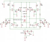
Thanks for the suggestions, I have simulated them - almost, i used two inductors instead of a single-centre tapped transformer.
Do you have a special reason to suggest a centertapped transformer?
Speakerload 8 Ohm.
Bias current for the outputfets is 4.3A, which is better than the previous 200A😀 .
The output inductors is 33mH as suggested elswhere in this thread.
The inductors at the inputstage needs to be as high as 680mH but needs only to take 50mA.
Output bias is adjusted by VR1 and VR2.
This Circiut is not ment to be ready to bulid, but more to evaluate this topology, all though i am shure it will work, but how does it sound?
I am not used to work with inductors, so i have to study that issue a some more before i take this further.
djk
Unfortunately i can´t get the pdf file you pointed out.
Regards
Attachments

"djk
Unfortunately i can´t get the pdf file you pointed out."
Works for me, but try this instead:
http://home.kimo.com.tw/skychutw/
Then go to:
"Circuits"
And then to:
"Hadley 622"
It is a pdf file so you need Adobe (free).
http://homelf.kimo.com.tw/skychutw/Circuits/Hadley622.pdf
You must have Active X enabled in your security settings, I can't run TIFF files at work for this reason.
Your new circuit looks better.
The resistor plus bootstrap cap in the Hadley serves the same function as the 680mH choke does in your new circuit.
djk
Thanks for you kind answer!
I tried enabeling the activex to the lowest level. I can get the page http://home.kimo.com.tw/skychutw/ but still can´t get the pdf.
I have the reader installed.
I will give it an other try later.
I have found some litreture about bootstrapping on the net, which i will read when i get the time to do so.
To day i will finish my new xsoz.
Thanks again
regards
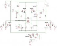
Yes. It guarantees that as Q101 drain goes up for example, Q6 drain goes down by exactly the same amount. With two separate inductors they not locked to each other but are free to move independently which is not good.Henrik said:i used two inductors instead of a single-centre tapped transformer.
Do you have a special reason to suggest a centertapped transformer?

- Status
- Not open for further replies.
- Home
- Amplifiers
- Pass Labs
- Choke Loads for Zen/Aleph Amps