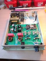
I am looking purely practically, I have various opamps, SOIC and DIP. As much as it's argued, it still doesn't sound the same. Otherwise, I make such simple devices point to point. At least for a test. It's always better and easier to work on a PCB, but for one piece, point to point and you try everything out nicely. This in the picture is very similar, opamp + BJT output stage with VBA multiplier. This is a headphone amplifier. PSU is CRC, and then 7815/7915.Why not, both are abundantly available. Besides almost any decent op-amp will do. I used TL081 and sounds great. I would rather put a dip package and SOIC, it would be easier as pinout is the same, just wider as NIXIE recommends.
Attachments
Last edited:

Hi guys
I don't have enough time to change concepts every day, taking into account individual suggestions
in my head I'm already in other projects ;-)
So....
I'm thinking about making a "really final" version of this amplifier
I want to put two channels and a power supply on one board (less cables, less problems with ground loops etc. etc.)
Now - to finally make everyone happy I need your opinion
1) Power supply:
CRC or regular?
Bridge rectifier or discrete diodes?
Separate rectifier for each power supply branch or one common?
2) Amplifier:
SMD or THT version?
Capacitor on the input - yes or no?
Transistors under the board or on the edge?
OP-amp - two versions - SOIC and DIP - I can do that
Any other suggestions?
think about it and on this basis I will try to do something this weekend
Schottky diodes rectifier, CRC filtration, independent stabilized power supply for each channel, it is certainly the best option, and the most expensive. The input capacitor is needed mostly only for the NE5534. It can be optionally added outside the PCB if one thinks it is necessary. Especially if somebody take a big boutique capacitor, it will take up half the PCB. TH is more practical for most users, it doesn't bother me, I've already perfected SMD soldering. I have a Hitachi SJ50/SK135, so it doesn't really matter to me how the plastic transistors are positioned. I'll have to figure out how to mount and connect TO3. And I have Burson/Sparkos opamps, so DIP 8 means a lot to me. Sorry if I'm boring. 🤣
Last edited:
My suggestion:
You have to listen all parts.
Most of the Shottkys I heard were unsuitable for audio.
No channel separated psus, because even the same parts of one batch modulate the signal audibly differently. Therefore:
an active control can only consist of highly selected parts.
You have to listen all parts.
Most of the Shottkys I heard were unsuitable for audio.
No channel separated psus, because even the same parts of one batch modulate the signal audibly differently. Therefore:
an active control can only consist of highly selected parts.
mp
Regular
Discrete diodes
One common
2) Amplifier
THT holes
Yes, cap on the input
Transistors on the edge
SOIC opamp
1) Power SupplyHi guys
I don't have enough time to change concepts every day, taking into account individual suggestions
in my head I'm already in other projects ;-)
So....
I'm thinking about making a "really final" version of this amplifier
I want to put two channels and a power supply on one board (less cables, less problems with ground loops etc. etc.)
Now - to finally make everyone happy I need your opinion
1) Power supply:
CRC or regular?
Bridge rectifier or discrete diodes?
Separate rectifier for each power supply branch or one common?
2) Amplifier:
SMD or THT version?
Capacitor on the input - yes or no?
Transistors under the board or on the edge?
OP-amp - two versions - SOIC and DIP - I can do that
Any other suggestions?
think about it and on this basis I will try to do something this weekend
Regular
Discrete diodes
One common
2) Amplifier
THT holes
Yes, cap on the input
Transistors on the edge
SOIC opamp
I am okay with Lineup choice. You are really spoiling these guys Zoltan. Let me thank you on everyone's behalf.
I have been away for a few days and am just now jumping in. I really like this design, and I think that the notion of simple arrangements of opamps and lateral MOSFETs deserves more exploration. As we start to delve into using DSP crossovers and bi-amping—or even tri-amping—systems, small, high-quality amplifiers for driving the midrange and tweeters will be very important. The laterals are very nice in this application, as they are essentially indestructible at these power levels, and there is no need for elaborate protection schemes, at least for the amplifier.
My application is for my ongoing adventures with my vintage Klipschorns. Amps such as this are small and simple enough that four or even six could be built into a single chassis, along with the active crossovers/DSP units.
Keep up the good work.
My application is for my ongoing adventures with my vintage Klipschorns. Amps such as this are small and simple enough that four or even six could be built into a single chassis, along with the active crossovers/DSP units.
Keep up the good work.
I post my chosen circuit for any newcomers.
This is what we aim for in this thread.
It can deliver 10 Watt RMS into 8 Ohm.
And even more into 4 or 6 Ohm.

This is what we aim for in this thread.
It can deliver 10 Watt RMS into 8 Ohm.
And even more into 4 or 6 Ohm.
So here we go...
common rectifier - MUR diodes (TO220)
capacitors 35 mm diameter
OP-amp-SOIC
several sizes of capacitors at the input
Question - should the diodes be placed on a common radiator with the power transistors?
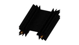
Or will I optionally add additional small radiators of the SK104 type, one for each of the two diodes?
common rectifier - MUR diodes (TO220)
capacitors 35 mm diameter
OP-amp-SOIC
several sizes of capacitors at the input
Question - should the diodes be placed on a common radiator with the power transistors?
Or will I optionally add additional small radiators of the SK104 type, one for each of the two diodes?
Attachments
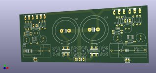
Add small radiators of the SK104 type.So here we go...
common rectifier - MUR diodes (TO220)
capacitors 35 mm diameter
OP-amp-SOIC
several sizes of capacitors at the input
Question - should the diodes be placed on a common radiator with the power transistors?
Or will I optionally add additional small radiators of the SK104 type, one for each of the two diodes?
Isn't it 4 diodes??
@ZoltanChivay
Look alright to me.
Stereo in one PCB. Super!
Can not see C11 in your PCB. C11 in my schematic. R18 + C11 in the output.
Look alright to me.
Stereo in one PCB. Super!
Can not see C11 in your PCB. C11 in my schematic. R18 + C11 in the output.
Last edited:
Looking good ZC👍🏻
Please add six mounting holes for M3 fasteners to support the board on standoffs.
One at each corner and middle on the long sides.
Please add six mounting holes for M3 fasteners to support the board on standoffs.
One at each corner and middle on the long sides.
Yes It's trueCan not see C11 in your PCB
From my experience - it's better to solder zobel network directly on the output terminals
Please add six mounting
Of course I will add it. It's just the first draft.
First attempt
Someting like this?
This is a neat, organized layout. Here are some suggestions :
I believe getting the bypass capacitors on the opamp would be a good idea per the manufacturer's recommendations. One of the downsides of using high-performance opamps is that they get more fussy about bypassing and track lengths to the input connections. Most opamp data sheets show a recommended layout near the end of the document. My experience has been that the faster the opamp, the more critical it is to follow their recommendations.
Also, I can't tell, but does the speaker return path go directly to the midpoint of the supplies, i.e., the big power supply filter caps? If the return current shares copper with signal currents, it increases the likelihood of oscillation or perhaps distortion.
Also, I can't tell, but is there a low-pass filter on the input to keep out RF, etc.?
I like this design and am keenly interested in how it turns out.
Zoltan, pleasing everyone is one of the most difficult tasks there is.
- Home
- Amplifiers
- Solid State
- Choctaw - 10 Watt Amplifier, 1 Opamp + 2 MOSFET