This is the final version.Guys Maybe we should first agree on a final version?
Is it hard to modify the PCB every now and then to make everyone happy?
I don't think I will change anymore.
It is the same as the version I posted before in the thread.
Your CRC power supply looks nice.
We could use it. If one does not want to use R we can short it out.

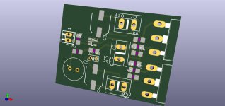
Amplifier board 45x90mm
Power supply board 100x73mm
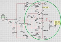
A diagram with part numbers and values is also attached
zip fies are gerbers
Please check the diagram for errors!!! I don't see it but....
For personal use for the diyaudio.com community
Power supply board 100x73mm
A diagram with part numbers and values is also attached
zip fies are gerbers
Please check the diagram for errors!!! I don't see it but....
For personal use for the diyaudio.com community
Attachments
Does MUR820 diodes need heatsinks?some old project of mine- CRC power supply
With MUR820 diodes and 4x 25mm diam caps
Tested and works
As per DS Vdrop is around 0.8V per diode, as in one half perion 2diodes are conducting this is voltage drop of 1,6VDC.
10W audio amplifier as per author schematic working with +/-16VDC gives around 14,2Vpeak, so current needed is 1,25A per rail.
0,8V x 0,625A gives total dissipation of 0,5W per diode.
To220 case to ambient is 70C/W so 35C wil be raised temp over ambient temperature of 25C and total temperature of single MUR820 will be 60C and that is very hot for semiconductor.
Add heatsink to diodes or use bridge rectifier mounted under the pcb to case to cool it down.
In my opinion no heat sink required, 0,5 watt per diode is nothing and each diode only conducts half the time so in essence 0.3 watt. Beside they only replenish the used energy stored in the reservoir capacitors per half cycle. They may heat up a little before the first second expired after turn on when capacitors are empty.
Last edited:
Rule of thumb is 1000uF/Amp. Lineup is using 10x that is needed so the caps will have only mild ripple and should not pose any problems. Besides the transformer would start limiting current at start up due to its own resistance. So what I am saying is choose the transformer size needed and not Mega VAs. I would argue that a 80VA transformer for both channels would be more than adequate running the output in class A. If running in class AB I would half the rating, there is enough energy stored in the capacitors. We must also remember that with audiophile bigger is better.
I use this power supply with a 2x25W amplifier and I do not use radiators on the diodesDoes MUR820 diodes need heatsinks?
If your sound source has a capacitor at the output (if you are 110% sure about it!) we can skip the input capacitor in the amplifier
If someone cares about space - here is a mini version with smd elements 48x36mm
I left the capacitor in the feedback through so that I could use green Muse ;-) or something like that
The compensation capacitor is also tht
If someone cares about space - here is a mini version with smd elements 48x36mm
I left the capacitor in the feedback through so that I could use green Muse ;-) or something like that
The compensation capacitor is also tht
Attachments
Most ancillary equipment has output capacitors, I am sure. What is more is that you have an input capacitor in the amp and one in the output of the ancillary equipment is in series and will affect the LF performance. I would say not to add the input cap, it can be added on the input if the user so please. What you think Lineup
Lineup
since U2 & U3 gates at input of your A-class OPS are boostraped via C6 & C7 I wonder what is the average OPS input impedance ? , in that configuration I guess that is probably very high ? , but enough high to be well driven with one linear small signal tube ? ,
(hope that I`m not off topic to much !)
Best Regards !
Attachments
Last edited:
but still two-layers 😉That is a very nice little board, and will be less expensive.
OPA1655 is available in SOIC.If your sound source has a capacitor at the output (if you are 110% sure about it!) we can skip the input capacitor in the amplifier
If someone cares about space - here is a mini version with smd elements 48x36mm
I left the capacitor in the feedback through so that I could use green Muse ;-) or something like that
The compensation capacitor is also tht
Seems like you have added SOT-23 in your PCB.
SOIC it should be
Nice job. Can I ask on behalf of the DIY guys here that may not be able to open the Gerber, to plot a 1:1 negative of top copper, bottom copper (mirrored), and component layout and post it in PDF format, some will want to make their own PCBs at home.
according to the datasheet we have two variants of the housingOPA1655 is available in SOIC.
Seems like you have added SOT-23 in your PCB.
SOIC it should be
I chose SOT
In soic 3 pins are unused So why bother soldering them?
Only two vias???? 🤣 Why SOT23, because most people here will think it is an ant and try to kill it.
Can I ask on behalf of the DIY guys here that may not be able to open the Gerber, to plot a 1:1 negative of top copper, bottom copper (mirrored), and component layout and post it in PDF format, some will want to make their own PCBs at home.
Attachments
The impedance seen by the opamp output is 7567 Ohm. This is the Class A version posted earlier. With bootstrap.Lineup
since U2 & U3 gates at input of your A-class OPS are boostraped via C6 & C7 I wonder what is the average OPS input impedance ? , in that configuration I guess that is probably very high ? , but enough high to be well driven with one linear small signal tube ? ,
(hope that I`m not off topic to much !)
Best Regards !
At 1 Watt Output 1 kHz in to 8 Ohm
Holy crap that PCB is the same size as the two MOSFET. One can build it inside a headphone cup. This PCB will definitely not impress your audiophile friends so keep the chassis sealed. 🤣 🤣
- Home
- Amplifiers
- Solid State
- Choctaw - 10 Watt Amplifier, 1 Opamp + 2 MOSFET