I am using your schematic called Choctaw_21_final from post #322 with C4=10pf. I have done more tests and kept the amplifier turned on fot a hour or so and I don't see oscillations. I am now using much smaller heatsinks compared to the ones on my picture at post #365 and they work fine. I also replaced the 100VA 12+12v transformer with a smaller 40VA one. and increased the 10K feedback resistor to 22k.
The AC voltage measured on the power transformer is 12.4+12.4V and the rectified DC is about 15+15V. It was sligthly more with the bigger transformer, due to the better regulation, but 15V seems ok for me.
There is something not quite right about the power draw from the transformer, and is related to the hum I experienced before. I have meeasured the current draw with an AC clamp ammeter on each one of the 3 wires connecting the transformer to the board. The values are 400mA on the left AC terminal, 50mA on the 0v (common) terminal, and 450mA on the right AC terminal when both channels are connected. They are 450mA , 50mA and 500 mA when only one channel is powered. On this instance, the AC is 13+13V and the rectified DC is 16+16V.
I had to wire the transformer connection of the second channel in the opposite way compared to the first channel, otherwise I hear the loud background hum that was present when I populated both channels on the same board. This means that the common (0V) connection of the transformer is connected to the common connection of both boards; the left AC connection of the transformer is connected to the left AC of the first board an to the right AC of the second board; and viceversa. This way the total current draw from each transformer windings is identical, at least when both channels are at rest.
Not sure about the cause of this imbalance.
The residual DC at the speaker terminals is very low: 0.9 mV on the first channel and 0.3 mV on the second channel. There is no pop or bad noise both at turn on and at turn off.

I have tested the amplifier with better speakers and I had to install a 10 ohm hum breaking resistor to manage the ground loop. Still not totally silent with the high efficiency speakers, probably because my transformer does not have a magnetic shield, so I will later try to replace the transformer with two 19V switching power supplies. This circuit seems to benefit from a stabilized power supply anyway, a small change on the power supply voltage does cause a larger variation of the idle current on the mosfets. This seems to be the only drawback of this amplifier, the sound is clean. I have increased again the feedback resistor value.

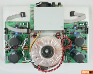
I replaced the transformer with two 16V 50W quality switching power supplies (double insulated, without earth connection, and fully shielded) with additional 30mH inductor at the output to filter out the residual high frequency noise. The last tiny hum/buzzing residue disappeared. The amplifier is now silent and works well. Next I will remove the bridge rectifier, tidy up the wiring and continue testing.
Good news !The last tiny hum/buzzing residue disappeared. The amplifier is now silent and works well.
are you using 2pcb or 1?
I am using 2 PCB, with the noisy channel cutted off, stacked toghether. The board on the back is the DC power supply (the transformer was there previously).

@minek123 and anyone offering LTspice advice,
I'm nearly a complete noob with Spice and am trying to learn my way by extrapolating from working asc files. The asc file in post #211 is of particular interest because it includes an OPA1656 and directives to generate an FFT, but I can't get it to execute--- probably due to a missing library file. Can you nudge me in the right direction?
Many thanks for copying your work and experience!
I should have mentioned I'm using LTSpice 17.2.4 on a MacBook Air. Thanks again.
Attachments
Last edited:
What kind of error are you getting? Is there a log file?
Your sim works fine on my PC - LTSpice XVII(x64) 17.0.37.0

I suspect newer versions of LTSpice may not allow loading libraries from http:// urls. They may only allow 'safe' https:// urls.
Newest LTPsice version 24 doesn't load libraries from any URLs, even from https://. Not sure about Mac versions.
Workaround - download the library files from the urls in the sim (using internet browser) to your computer, and load them to your sim as local files, rather than URLs.
Edit: 2 lib files from your sim zipped and attached to this post.
Your sim works fine on my PC - LTSpice XVII(x64) 17.0.37.0
I suspect newer versions of LTSpice may not allow loading libraries from http:// urls. They may only allow 'safe' https:// urls.
Newest LTPsice version 24 doesn't load libraries from any URLs, even from https://. Not sure about Mac versions.
Workaround - download the library files from the urls in the sim (using internet browser) to your computer, and load them to your sim as local files, rather than URLs.
Edit: 2 lib files from your sim zipped and attached to this post.
Attachments
Last edited:
Still waiting for transistors ....
I'm thinking about the problems with the hum ...
Wouldn't it be easier to design a new PCB - one channel, without a power supply? Based on that part of the complete PCB (Full) that doesn't cause problems?
Like I wanted to do at the beginning?
I'm thinking about the problems with the hum ...
Wouldn't it be easier to design a new PCB - one channel, without a power supply? Based on that part of the complete PCB (Full) that doesn't cause problems?
Like I wanted to do at the beginning?
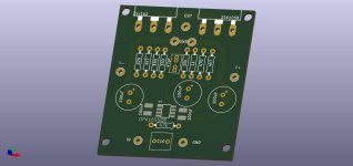
You can consider HBR, easy to use 0R in case there is no need, however cutting the traces hurts all.
I like it. Power supply is best relegated on a separate board, as I have ultimately done on my build. It would be nice to have V+, V- and ground lined up on the same side of the board, this will ease wire routing. I like to use pluggable terminal blocks on experimental circuits, this way I can remove the board quickly and easily without desoldering the wires. It would also be useful to have the same spacing between the mosfets as in your previous board. This way I will not need to drill again my heatsinks. I am using the amplifier on my main system now. No issues when driven by a low impedence source, but I cannot add a passive volume potentiometer because any source impedence greater than a few hundred ohms results in background hum. So I am happy to see that you are working on a new board.Something like this?
This was an external firewire case for Apple computers from early 2000. Many of them, like this one, have a thick anodyzed alluminium body to match the aestetics of the first generation Mac pro. They were bloody expensive back then but now they are useless and discarded or sold at scrap value. They are very good for housing small amplifiers or preamps.@pcan
What is the origin of your aluminum case ? I like it
I guess I'm working too fast...So I am happy to see that you are working on a new board.
Too late to change - I just ordered new single PCBs from JLCPCB.
I also have an idea for PCB modification in the FULL version. I will work on it.
Brilliant idea.This was an external firewire case for Apple computers from early 2000. Many of them, like this one, have a thick anodyzed alluminium body to match the aestetics of the first generation Mac pro. They were bloody expensive back then but now they are useless and discarded or sold at scrap value. They are very good for housing small amplifiers or preamps.View attachment 1432947View attachment 1432948View attachment 1432950
I will copy you without any remorse 😁
I love the simplicity here. One op-amp and 2 MOSFETs. Nice. And being an old Hafler guy, I wonder if anyone here has taken this idea to a 100W application. With dual pairs of MOSFETs and 60V or so on rails. We would of course need a higher voltage op-amp - like this: https://www.ti.com/product/OPA462#description
With a higher voltage supply and an op-amp that is OK with +/- 60V, we can run the MOSFETs at say 150mA each and have a nice class AB amp. Still simple. And could be built in an old Hafler chassis.
Seems to work on paper - but has anyone tried?
With a higher voltage supply and an op-amp that is OK with +/- 60V, we can run the MOSFETs at say 150mA each and have a nice class AB amp. Still simple. And could be built in an old Hafler chassis.
Seems to work on paper - but has anyone tried?
- Home
- Amplifiers
- Solid State
- Choctaw - 10 Watt Amplifier, 1 Opamp + 2 MOSFET