This is getting quite exciting guys. But whatever Lineup sees fit is okay, he knows what he is doing from experience.


I am going to be pedantic and say the three connectors would look nice if they where horizontally lined up. Also the power transistors should not be clamped to the heatsink by the PCB else the underside of the connectors will push holes into them. So the power transistor mounting hole should have a diameter bigger than m3 screw head and the power transistor clamped by the screw only. Sorry, I am a bit of a visual perfectionist. I can't stand pictures not lined up on the wall. 😱
Even more considering the thread starter's nick. 😊I can't stand pictures not lined up
Thank you for your commentsI am going to be pedantic
The mounting screw hole is 5.5 mm in diameter I use M2.5 screws. It fits perfectly
The connectors are used on the PCB only as a "footprint" I ALWAYS solder the cable directly to the PBC
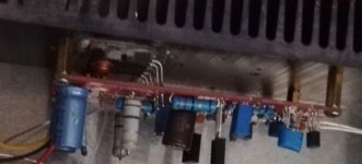
If you use long enough spacers - nothing will touch (see photo)
But if these details bother you You can always modify the PCB based on the gerbers in KiCAD
Attachments


2W resistor +18V zeners +Caps?I would feed the output stage with RAW DC +-25V and stabilize the supply voltage for the OPA with a 7815/7915 or similar.
There are these new upgraded 78/79XX from ON. I used them in a Whammy headamp. It's good, simple to use and cheap. Maybe some light CRC in front of the regulator?
Guys Maybe we should first agree on a final version?
Is it hard to modify the PCB every now and then to make everyone happy?
Is it hard to modify the PCB every now and then to make everyone happy?
I agree, we should not hijack Lineup's thread, he should decide how to proceed, what to add and what to discard.
I made PCBs for my own needs, taking into account my personal limitations (age, vision problems)Zoltan, what about using surface mount resistors, say 1206 size
SMD components are something I avoid as much as I can
Considering the prices of making PCBs, for example in JLC PCB, IMO making a single-sided board does not make much sense
If we do not strive to minimize PCBs - then there will be large "audiophile grade" electrolytic capacitors anyway
Power supply "on board"?let us focus on supply + amplifier.
so we have to make dual-mono (two transformers or one with of 4x12V)
Powering the OP-AMP with 15V limits the output voltageI would feed the output stage with RAW DC +-25V and stabilize the supply voltage for the OPA with a 7815/7915 or similar.
So powering the output stage with a higher voltage won't give much more power
I may be wrong but the output stage has a gain of 1 (theoretically) so the output voltage at the amplifier's output will depend only on the signal level at the OP-AMP output
Of course, there is a drop on the output Transistors but I personally don't see much sense in this change

Onsemi Part numbers?There are these new upgraded 78/79XX from ON. I used them in a Whammy headamp. It's good, simple to use and cheap. Maybe some light CRC in front of the regulator?
Thanks
Last edited:
- Home
- Amplifiers
- Solid State
- Choctaw - 10 Watt Amplifier, 1 Opamp + 2 MOSFET