Thanx for Your commentsbypass capacitors on the opamp would be a good idea
Yes-good idea -two small smc ceramic aps near op-amp !
Ask LineUp ;-) Im just pcb-maker 🤣but is there a low-pass filter

There is no need, in my opinion, for a low pass filter on the input.This is a neat, organized layout. Here are some suggestions :
----
Also, I can't tell, but is there a low-pass filter on the input to keep out RF, etc.?
I like this design and am keenly interested in how it turns out.
Because with that 68pF compensation cap the upper bandwidth is 'only' like 200kHz.
We can say the amplifier itself has a built in low pass filter.
Those afraid can even use one 100pF comp cap.....
Yes It's true
From my experience - it's better to solder zobel network directly on the output terminals
I see. That is okay, Zoltan.
unless you are prepared to model your speaker and cross over, then a Zobel is really a waste of time. It only screws with you response.
Zoltan, beautiful PCB!! I could not do it better even if I was paid, excellent work. I am proud to know you.
Last edited:
Yes, the PCB is fantastic.
I agree really with Nico Ras.
Now let us drag people here to build this thing.
Let several persons use this PCB.
I agree really with Nico Ras.
Now let us drag people here to build this thing.
Let several persons use this PCB.
I'm gonna say .... my opinion is simple ... I don't have the time for a big point to point project, so any thing like this project with a single PCB with power suplly and 2 channels. is perfect. .... i'm just getting on this thread, its evolving so fast, I honestly thought it was months long not days. SO there is obviously interest here. I was going to do a mosfet amp, but this look more fun.
I always get hammered with pop ups from Ali Baba because ive bot a lot of DIY parts through AliExpress ... this just popped up... perhaps we might want to look at some pre fabbed casses to keep board measurement connected to? Also, most of these places will customize for pretty cheap. It might be worth connecting with one and getting a price idea. Maybe a little early for this ..Just thinking.
https://www.aliexpress.us/item/2255...jLYmtc2Pt7QaAgD7EALw_wcB&gatewayAdapt=glo2usa
https://www.aliexpress.us/item/2255...jLYmtc2Pt7QaAgD7EALw_wcB&gatewayAdapt=glo2usa
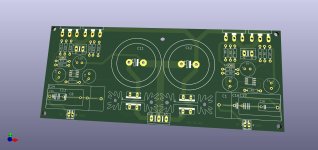
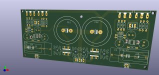
In attachments gerber files, schematic with element numbering and values
I added decoupling capacitors (smd size 1206) around the op-amp
From my side - work done
Thank you for the time spent together
It's a pleasure for me to work with a great community
If our joint work bears fruit - it will be nice to read about the effects
See you in the next project!
I added decoupling capacitors (smd size 1206) around the op-amp
From my side - work done
Thank you for the time spent together
It's a pleasure for me to work with a great community
If our joint work bears fruit - it will be nice to read about the effects
See you in the next project!
Attachments
Those boxes from Alibaba is really inexpensive and pretty nice. I don't think it is even possible to buy the raw material for that price. I don't have a workshop or material, but if someone has a piece of 3mm thick aluminium plate of 0.036 square meter, place two ten watt power resistors on it and run them with with 16V and 800 mA each and establish how hot it gets. If it is adequate then one may not need additional heat sink but only use the bottom plate of the box as heat sink. Placing the power transformer outside some distance away, will also help with any stray induced hum and noise.
Last edited:
Good recommendations for those new to jlcpcb:
https://www.diyaudio.com/community/...-walkthrough-featuring-the-fab-jlcpcb.404905/
https://www.diyaudio.com/community/...-walkthrough-featuring-the-fab-jlcpcb.404905/
- Home
- Amplifiers
- Solid State
- Choctaw - 10 Watt Amplifier, 1 Opamp + 2 MOSFET