What do you think about the regulated power supply?Your CRC power supply looks nice.
We could use it. If one does not want to use R we can short it out.
The power of the amplifier is not high so there should be no problems....
IMO a regulated power supply would help to get the most out of this simple circuit
Don't worry - we will still be going around LineUP projects 🤣

Regulated is to prefer, of course.What do you think about the regulated power supply?
The power of the amplifier is not high so there should be no problems....
IMO a regulated power supply would help to get the most out of this simple circuit
Don't worry - we will still be going around LineUP projects 🤣
That way we could use 2x15VAC transformer and perhaps raise the supply to 2x18VDC. Or at least 2x17VDC.
LM317 + LM337 is one favorite. They are quite good.
With raised supply comes change in the bias of MOSFET, but that is all changes needed.
I was thinking about something elseRegulated is to prefer, of course.
Remember this?
https://www.diyaudio.com/community/...ators-15v-with-good-performance.402125/page-2
I built this power supply in several copies.
It works perfectly with my headphone amplifier (based on your Cello amplifier - but with a few of my modifications), with a few DACs
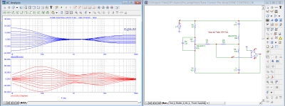
I made a project of a more powerful version of this power supply specifically for a small amplifier
In LT Spice it looks very good - but the prototype has not been created yet
I think that this amplifier with this power supply will be it!
Attachments

At least there will be something to see in the box.
Lineup, I have another curved ball. This project can go on forever. Wat about variable LP and HP filters so some DIYers can change their speakers to active. Am I going to far? 🤔
Lineup, I have another curved ball. This project can go on forever. Wat about variable LP and HP filters so some DIYers can change their speakers to active. Am I going to far? 🤔
Hi, tuning into this project a bit late. This looks like exactly the project I'm looking for. There seems to be a couple long threads here in terms of where this is at currently. Can some one sum up everything here? :
1 - has anyone made any PCBs ? Is there a final set of gerber files?
2- Is there a full 2 channel board design? or are they all mono?
3- Final power supply design and PCB/Gerber file
Thanks for the help:
Tim
1 - has anyone made any PCBs ? Is there a final set of gerber files?
2- Is there a full 2 channel board design? or are they all mono?
3- Final power supply design and PCB/Gerber file
Thanks for the help:
Tim
I did this with LF353 and Irfz40 and irf9z40 years ago.
Biased at 5.6v provided 25w at 14.4 volts.
At 33 volts would do 100 watts into 4 ohms
Great little amp.
Running bridged for power.
Biased at 5.6v provided 25w at 14.4 volts.
At 33 volts would do 100 watts into 4 ohms
Great little amp.
Running bridged for power.
Final set of gerbers-post 62 (pcb-mono , power supply CRC(mono)1 - has anyone made any PCBs ? Is there a final set of gerber files?
2- Is there a full 2 channel board design? or are they all mono?
3- Final power supply design and PCB/Gerber file
post 72 -gerbers wersion smd (mono)
I've tested power supply
Amp's PCB NOT TESTED
Regulated power supply -NOT TESTED
This time - there will be no Gerbers - until I test the device
I have not done PCBs for over five years, but I guess with time I can lay PCBs for above two options if anyone is interested. The pot will be wired to the boards simply because I don't have pots in my library and creating them is a shlep. Anyway that is me for now. A friend has arrived who is taking me grocery shopping 
PCB 66x46mm soic+tht+input capI am waiting for a PCB with through holes and SOIC for the opamp.
gerbers
Attachments
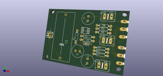
I would add two or three more holes for the input capacitor so that smaller capacitors, with shorter hole spacing, can also be tried.PCB 66x46mm soic+tht+input cap
gerbers
My eyes do not recognize whether the little power caps are between the voltage connection and the transistors - on pcb.. It may well be that the capacitors are better between - I don't know.
I would even advise leaving the capacitors off the board for reasons of homogeneity - but the board assembler can try it out for himself and listen and decide later.
- Home
- Amplifiers
- Solid State
- Choctaw - 10 Watt Amplifier, 1 Opamp + 2 MOSFET