Ss396
What a Car that was!
Kudos on paint job. 1st. thing that caught my eye. Worked in a paint shop 3 years. Really nice.
Bluto
What a Car that was!
Kudos on paint job. 1st. thing that caught my eye. Worked in a paint shop 3 years. Really nice.
Bluto
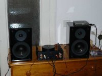
My first working amplifier😀
gainclone lm3886
http://img.w3dizajn.net/viewer.php?file=P10001902jkc.jpg
http://img.w3dizajn.net/images/P1000189teeq.jpg
i used the cheapest capacitors and the sound is beautiful...i`m 18. years old and i doesn`t have lots of money to buy a excellent parts.
😎
gainclone lm3886
http://img.w3dizajn.net/viewer.php?file=P10001902jkc.jpg
http://img.w3dizajn.net/images/P1000189teeq.jpg
i used the cheapest capacitors and the sound is beautiful...i`m 18. years old and i doesn`t have lots of money to buy a excellent parts.
😎
bego2 said:i`m 18 years old
Respet.
Attachments
Bego2 -
You ought to be proud of yourself. I'm 58 and still can't figure out how to build my 1st.
Bluto
You ought to be proud of yourself. I'm 58 and still can't figure out how to build my 1st.
Bluto
thanks...I have a little knowledge but i learn every day something new.
I`m very satisfied with sound. These are my diy speakers that i made when i had 17. years..i put the big distance between tweeter and midbass but the filter will fix that. 🙁 ...drivers are westra xv-165-1398-8 and tweeter TVM arv-104-04/8
http://img.w3dizajn.net/images/IMGP0335fxfh.jpg
http://img.w3dizajn.net/images/IMGP0355g2n3.jpg
sorry for putting images of speakers in the chip amp threid. 🙂
My small contribution....
Here is my small contribution to the gainclone community...
http://www.flickr.com/photos/16460801@N06/2263113144/in/photostream/
There are plenty of photos of my baby...and more coming (please excuse some of the pics...having camera issues).
I have almost completed another clone....a P2P LM3875 which is in the process of being tested...pics to come.
Thanks,
Wayne
Thought I'd post some pictures of my current project. It is a basic bridge-parallel implementation of the NSC LM3886. I have designed the boards to be as modular as possible. I am at the testing stage.
Pile of unseperated, unassembled boards:
Single amplifier board:
Buffer board:
Power supply board:
Soft start board:
* The 10 pin IDC connector attaches to a uC board, not pictured.
Enough assembled boards for a whole stereo amplifier:
Anyway, really looking forward to testing these. Just waiting on the heatsinks, should be done any day now.
Anton
Pile of unseperated, unassembled boards:
An externally hosted image should be here but it was not working when we last tested it.
Single amplifier board:
An externally hosted image should be here but it was not working when we last tested it.
Buffer board:
An externally hosted image should be here but it was not working when we last tested it.
Power supply board:
An externally hosted image should be here but it was not working when we last tested it.
Soft start board:
An externally hosted image should be here but it was not working when we last tested it.
* The 10 pin IDC connector attaches to a uC board, not pictured.
Enough assembled boards for a whole stereo amplifier:
An externally hosted image should be here but it was not working when we last tested it.
Anyway, really looking forward to testing these. Just waiting on the heatsinks, should be done any day now.
Anton
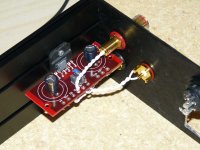
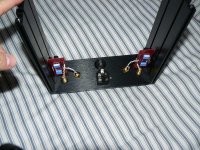
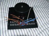
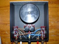
this is a rev.A lm3875 gainclone with PS and a big 300va 2x25v toroid in a hifi2000 enclosure, no pot, planning on using a pre (still undecided, probably a millet hybrid for now...maybe a kumisa soon).
i would apreciate some comments, specially regarding wiring, as i used what i had on hand.
i would apreciate some comments, specially regarding wiring, as i used what i had on hand.
Attachments

mekanoplastik said:...i would apreciate some comments.....
A dab of heatsink grease since the chip is on a groove, and a washer to help spread the pressure of the screw holding the chip down.
Those are suggestions, not requirements.
I "personally" would have used different color wires for the ps to avoid potential confusion but then, some times I can be... well, you know.
Absolutely beautiful execution.
bego2 said:My first working amplifier😀
gainclone lm3886
http://img.w3dizajn.net/viewer.php?file=P10001902jkc.jpg
http://img.w3dizajn.net/images/P1000189teeq.jpg
i used the cheapest capacitors and the sound is beautiful...i`m 18. years old and i doesn`t have lots of money to buy a excellent parts.
😎
Finally! There aren’t only old man (and women?) here! Haha

Since I discovered this forum, I’m getting very interested in the whole DIY audio thing.
I’m 19 and just finished my first amp, it will suddenly not be my last.
specs:
Transformer: 500VA toroidal (22V-0V-22V)
Rectifier: 8 x MUR860 (with 100nF capacitors and heatsinks)
Buffer capacitors: 25mF per rail (50mF total)
Amplifier: 2 x Bridged LM3886 setup (BR100)
Will do an approximately 100W to 120W per channel at 8Ohm.
I can't say anything about the quality of the sound because I still haven’t got good source/pre amp/speakers (any volunteers?).
All I can say the sound is very detailed, and it's _very_ powerful!
I really learned a lot of this project, for example that 200W is completely useless.
Normally I use 500mW and playing very loud maximum 10W, if I knew this I probably had build the single LM3886 setup.
Enough talking, here are the pictures:
An externally hosted image should be here but it was not working when we last tested it.
Clickable
An externally hosted image should be here but it was not working when we last tested it.
Clickable
An externally hosted image should be here but it was not working when we last tested it.
Clickable
An externally hosted image should be here but it was not working when we last tested it.
Clickable
An externally hosted image should be here but it was not working when we last tested it.
Clickable
An externally hosted image should be here but it was not working when we last tested it.
Clickable
An externally hosted image should be here but it was not working when we last tested it.
Clickable
An externally hosted image should be here but it was not working when we last tested it.
Clickable
An externally hosted image should be here but it was not working when we last tested it.
Clickable
The back plate is cut with an CNC water jet (I only made the Autocad drawling), heat sink is done manually.
Now I'm gonna build a preamp in an identical housing only less high. It will have an embedded system (8051) and perhaps a DAC.
Thanks for making this possible for me, keep up the good work!

Founded feedback is always welcome...
Robert
Nice amp Robert!!
1 suggestion: try to get proper solid copper rails instead of the aluminium ones.
1 suggestion: try to get proper solid copper rails instead of the aluminium ones.
RobertJ88
I'm 47 and I've just finished my first amp, it's nowhere near as good as yours, beautiful work by any measure.
John
I’m 19 and just finished my first amp
I'm 47 and I've just finished my first amp, it's nowhere near as good as yours, beautiful work by any measure.
John
- Home
- Amplifiers
- Chip Amps
- Chip Amp Photo Gallery