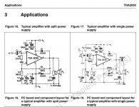
Nearly all opamps and ampchips can work with single supply.
Often in datasheet there are circuit examples for both dual and also single supply.
But a chip like TDA2003 is made for only single supply.
Often in datasheet there are circuit examples for both dual and also single supply.
But a chip like TDA2003 is made for only single supply.
Current drive on fullrange drivers revisited - with measurements made by Nelson Pass
https://www.6moons.com/audioreviews/firstwatt/firstwatt.html
https://www.6moons.com/audioreviews/firstwatt/firstwatt.html

Thank you lineup, looks sophisticated.
I got the LM1875 amplifier boards. I will study the schematic and find out to wire current feedback.
I got the LM1875 amplifier boards. I will study the schematic and find out to wire current feedback.
Attachments
-
 IMG_20230213_150628.jpg234.9 KB · Views: 146
 -
 IMG_20230213_150637.jpg197.8 KB · Views: 134
 -
 IMG_20230213_150647.jpg179.4 KB · Views: 130
 -
 IMG_20230213_150656.jpg215.8 KB · Views: 146
 -
 IMG_20230213_150717.jpg217.7 KB · Views: 133
 -
 IMG_20230213_150727.jpg284.7 KB · Views: 133
 -
 IMG_20230213_150734.jpg223 KB · Views: 128
 -
 IMG_20230213_150745.jpg195.9 KB · Views: 156
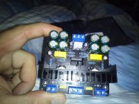
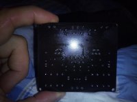
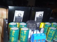
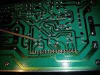
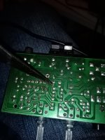
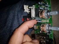
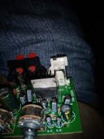
I checked the schematic of LM1875 boards I got.
They can be easily changed by cutting the trace where the 22 mfd capacitor is or the resistor lying in the way before it.
And soldering a wire with 100mfd in line directly to minus of the loudspeaker. 0,47 ohms then from minus back of the loudspeaker to ground, i. e. minus for the loudspeaker on the board.
I will try out unchanged board in comparison with the changed one.
Where my fingers are on the board are the mentioned points (22mfd capacitor and resistor)
Attachments
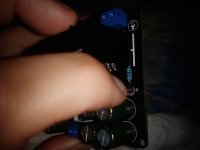
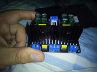
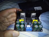
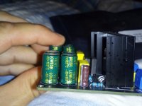
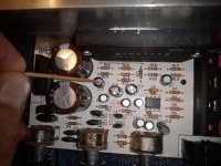
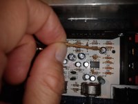
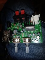
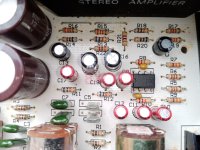
I checked now the stk4132 board for modification to basic current feedback.
Just going from pin2 and pin17 with a 100mfd capacitor directly to minus of the speaker. And adding current sensing resistor to ground. First the 560 ohm resistor from pin2+17 have to be off the board cutting this path.
Just going from pin2 and pin17 with a 100mfd capacitor directly to minus of the speaker. And adding current sensing resistor to ground. First the 560 ohm resistor from pin2+17 have to be off the board cutting this path.
Attachments
I'm curious how you find that board - I ordered one, it was indicated as delivered but I never got it - was refunded......
I got the LM1875 amplifier boards. I will study the schematic and find out to wire current feedback.
Please report your findings!
//
Yeah, I will make this time a record with music of a loudspeaker playing with the original board and in comparison to the modified board to basic current feedback.
With the pioneer TS 1310GF polypropylene car hifi fullrange loudspeaker you can hear easily any change in frequency response and distortion.
I already did a record after having changed the TDA2003 amp of which I only have one. However it would not have been fair to post it here because I already changed both stereo channels from 2.2 ohms to 0.1 ohms. So with voltage drive and 0.1 ohm the amp was much too loud - big amplification - what makes a comparison of voltage drive with current drive unfair. But already I had a good impression of what the difference is.
As I know very well the Pioneer fullrange - it does not work with voltage drive without EQ in the highs and lows - with current drive the driver was "automatically" sounding correct and very classy concerning distortion. Human voices were 100% correct with current drive. Like with the best high end loudspeakers.
I plan to build a loudspeaker with the Beyma 8agn which has also no copper ring / faraday ring on the pole piece. Both drivers profit from current drive.
AND - I have no problem with the bass - with current drive it just only sound correct - no need for EQing the bass down as several time to be heard in the forum whenever people talk only theoretically about the flaws of current drive.
Thanks for this fun thread, I am now also thinking about using current drive.
I have 10 LM3886 lying around, enough to fill 10 PCBs from JLCPCB.
So, I'm going to build something new, using 2 inverting stages.
The first stage uses a few inverting opamps in parallel, to be able to sink the current that the 2nd stage generates.
I aim for just a few Watts for a full range driver on my desktop, max RMS current 1A
1 side of a TPA1620 can do 700mA, 2 chips should be safe enough.
The stages will have different voltage supplies, to prevent the first stage from dissipating a lot of power.
Principal schema:
in this thread there is a suggestion for lm3886 in current drive, very simple to realize. watch here, no need to put something before it
https://www.diyaudio.com/community/...fication-to-current-drive.389985/post-7116745
https://www.diyaudio.com/community/...fication-to-current-drive.389985/post-7116567
https://www.diyaudio.com/community/...fication-to-current-drive.389985/post-7117206
Adason made this proposition
https://www.diyaudio.com/community/...fication-to-current-drive.389985/post-7116745
https://www.diyaudio.com/community/...fication-to-current-drive.389985/post-7116567
https://www.diyaudio.com/community/...fication-to-current-drive.389985/post-7117206
Adason made this proposition
i got two lm3886 from china one day I will try them out but they might be fakes as they were cheap
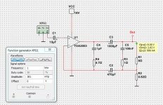
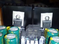
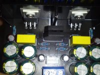
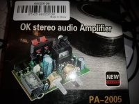
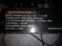
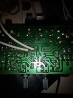
I got the amp boards with tda2005 which are now tda2004. Did not know that tda2004 exist.
Found out where to wire the feedback point.
The 470 mfd electrolytic is here 100mfd.
Will test the amplifier and report. Have a small fullrange driver 13cm named Eagle with aluminized cone what I did.
Eagle L022B Mk2 15,60 EUR
This driver profits a lot from basic current feedback as I use at the moment 9 ohms in line to make it sound much better. (Esa merilainens simple resistor method)
But current feedback should work better than the simple resistor method.
Attachments
-
 IMG_20230309_193754.jpg489.5 KB · Views: 115
 -
 IMG_20230309_193815.jpg430.4 KB · Views: 111
 -
 IMG_20230309_193900.jpg298.5 KB · Views: 117
 -
 IMG_20230309_193738.jpg383.5 KB · Views: 123
 -
 IMG_20230309_183826.jpg444.9 KB · Views: 132
 -
 IMG_20230309_183740.jpg429.9 KB · Views: 125
 -
 IMG_20230309_183726.jpg443.7 KB · Views: 121
 -
 IMG_20230309_183711.jpg687.7 KB · Views: 118
 -
 IMG_20230309_183656.jpg427 KB · Views: 111
 -
 IMG_20230309_183646.jpg460.3 KB · Views: 114
 -
 IMG_20230309_183633.jpg511.2 KB · Views: 118
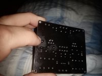
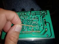
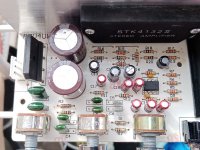
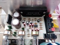
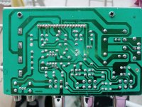
Somewhat off topic, but could you share your STK 4132 PCB design? If not as PDF or so, clear top and bottom pictures would already be a great help.
Attachments

Attachments

Nice lm1875 with preamp
https://m.de.aliexpress.com/item/10...lgo_pvid=a276718e-e71a-40e0-8cc2-809025c82f7a
https://m.de.aliexpress.com/item/10...lgo_pvid=a276718e-e71a-40e0-8cc2-809025c82f7a
Attachments

- Home
- Amplifiers
- Chip Amps
- Chip amp modification to current drive