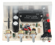
Here is my recommendation for CFA the LM1875.I bought now three stereo amplifiers LM1875 which I will try to make work with current drive/current feedback like in the schematic which I posted from this thread here. Three for 18 Euros from Aliexpress (directly from China). It will take some time until the amps arrive.
They are ready for use with a transformer 15-0-15 which has to be added. Hope I can do it. I will have to study the schematic and the parts on the board in order to find out how to change the wiring.
I already did that with a TDA2003 amp I bought. But now it is out of stock on Ebay and on Aliexpress. What is a pity.
Maybe LM1875 will sound better because there is no coupling capacitor needed.
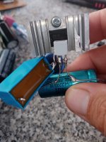
Here the modding of a ready made TDA2003 amplifier to current feedback:
https://www.diyaudio.com/community/...n-to-current-drive.389985/page-7#post-7225986
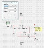
The capacitor C2 is needed for lower Vdc offset on output.
Otherwise you end up with 4-5mV offset.
Attachments

Thanks lineup! Could you please indicate what to change if I's wanted the lowest gain possible.
I will experiment with this amp for a 18sound 1095ND CD and dont want to do to much digital attenuation.
These are 16 ohm version but I now run them with 24 ohm in series driven by a small Anaview amp but still need 9 dB digital att.
//
I will experiment with this amp for a 18sound 1095ND CD and dont want to do to much digital attenuation.
These are 16 ohm version but I now run them with 24 ohm in series driven by a small Anaview amp but still need 9 dB digital att.
//
The current sense resistor does not have to be in the speaker return/ground. It can be in the supply rails or between the output and the speaker.
https://e2e.ti.com/support/amplifie...m/532277/constant-current-source-using-op-amp
https://www.edn.com/op-amp-can-source-or-sink-current/

This means that, yes, you can current drive a bridged amplifier. Since you are defining the current with the first amplifier, the second amp just increases the potential voltage available.
But I don't think actual current drive is a good idea. A better idea is a defined impedance that matches the speaker, which is also possible, but a bit tricky math wise, mixing negative and positive feedback. I did this years ago to match a 600 Ohms telecom application and modems did this.
https://www.researchgate.net/figure...ed-with-current-mode-amplifier_fig2_271530002
https://e2e.ti.com/support/amplifie...m/532277/constant-current-source-using-op-amp
https://www.edn.com/op-amp-can-source-or-sink-current/
This means that, yes, you can current drive a bridged amplifier. Since you are defining the current with the first amplifier, the second amp just increases the potential voltage available.
But I don't think actual current drive is a good idea. A better idea is a defined impedance that matches the speaker, which is also possible, but a bit tricky math wise, mixing negative and positive feedback. I did this years ago to match a 600 Ohms telecom application and modems did this.
https://www.researchgate.net/figure...ed-with-current-mode-amplifier_fig2_271530002
The change should be the 0.47 resistor.Thanks lineup! Could you please indicate what to change if I's wanted the lowest gain possible.
I will experiment with this amp for a 18sound 1095ND CD and dont want to do to much digital attenuation.
These are 16 ohm version but I now run them with 24 ohm in series driven by a small Anaview amp but still need 9 dB digital att.
//
Gain is 8/0.47 which is like 17.
If you take a 1 Ohm resistor you get Gain = 8.
Keep in mind the specified minimum stable gain of 10you get Gain = 8
(Or is that not applicable here?)
You are right, I think.Keep in mind the specified minimum stable gain of 10
(Or is that not applicable here?)
In this case we can use only 0.8 Ohm or lower.
I think 0.82 Ohm will be okay. This gives gain 8/0.82 which is close to 10.
Another thing.
8 Ohm speakers can have other impedances than 8 Ohm.
Probably 5 or 6 Ohm in some part of the frequency.
So, I would say a value of 0.47 Ohm should be a good thing.
Otherwise the Gain = 10 rule of LM1875 is violated.
8 Ohm speakers can have other impedances than 8 Ohm.
Probably 5 or 6 Ohm in some part of the frequency.
So, I would say a value of 0.47 Ohm should be a good thing.
Otherwise the Gain = 10 rule of LM1875 is violated.
Perhaps one should linerize the driver impedance with a conjugate link before doing this?
First I will try it without any alterations 🙂
//
First I will try it without any alterations 🙂
//
Gain = 16/resistor value.So with my 16 ohm (10?)
The calculation is: driver / Res > 10 ?
//
16/10 = 1.6
For gain=10 you can use 1.5 ohm.
But to be safe I should use 1 Ohm which give Gain=16/1 = 16
Conjugate link is the perfect way.Perhaps one should linerize the driver impedance with a conjugate link before doing this?
First I will try it without any alterations 🙂
//
It keeps the speaker impedance close to nominal impedance.
What wattage on R3?
C2 = 100uF... if I know I will only run the amp from say the absolutely lowest... 500 Hz - can I make it smaller?
//
C2 = 100uF... if I know I will only run the amp from say the absolutely lowest... 500 Hz - can I make it smaller?
//
Probably 5 or 6 Ohm in some part of the frequency.
Otherwise the Gain = 10 rule of LM1875 is violated.
The gain-of-10 limit applies above the audio band. You could run unity gain at 500Hz as long as the gain is let-out above 5kHz. The usual voice-coil does that naturally. (No, you do not want unity gain, even for horns, just an example.)
The power BW I need is between 1k-20k. For a compression driver. Change my mind about 500 - my Xo is 1,6k but I would like some margin...
Situation now:
This matches my 4 4" basses.
I would like to get rid of the 24 ohms resistors and shave of a few of the DSP att dBs...
//
Situation now:
- 21 dB gain amp
- 24 ohm in series of a 16 ohm driver (10?)
- 9 dB attenuation in DSP.
This matches my 4 4" basses.
I would like to get rid of the 24 ohms resistors and shave of a few of the DSP att dBs...
//
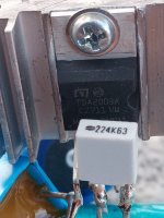
R3 should be at least 2.62 Watt.What wattage on R3?
C2 = 100uF... if I know I will only run the amp from say the absolutely lowest... 500 Hz - can I make it smaller?
//
This is with +/-24 Volt supply and R3=0.47 Ohm and 8 Ohm speaker.
So I would say it should be a 5 Watt resistor.
The capacitor C2 can be anything from 10u to 100u.
It does not affect the upp bandwidth. It stays at 300kHz in any case.
C2 affects the lower bandwidth, -3dB.
10uF = 7Hz
100uF = 2 Hz
And between those C2 can be 22uF, 47uF, 68uF
Thanks lineup!
As I will only use this for >1kHz, would say 1 uF be OK for C2 or is there a stability issue with that?
//
As I will only use this for >1kHz, would say 1 uF be OK for C2 or is there a stability issue with that?
//
1 uF will be okay.Thanks lineup!
As I will only use this for >1kHz, would say 1 uF be OK for C2 or is there a stability issue with that?
//
It makes the bandwidth 60Hz - 300kHz
There are no issues with that.
Making a hard wired TDA2003 now.
Does anyone know, do I need the Zobel of 100nanofarad and 1 ohm for the TDA2003 if I never put a capacitive load like piezo tweeters on the output?
I only use fullrange drivers with a voice coil and nothing else. No network at all.
Can I leave the Zobel out then?
Does anyone know, do I need the Zobel of 100nanofarad and 1 ohm for the TDA2003 if I never put a capacitive load like piezo tweeters on the output?
I only use fullrange drivers with a voice coil and nothing else. No network at all.
Can I leave the Zobel out then?
Attachments


Last edited:
- Home
- Amplifiers
- Chip Amps
- Chip amp modification to current drive