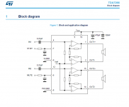
I wonder if someone tried to make from a chip amplifier a current amplifier design (inspired by Esa Merilainens - current drive info Website) if that is technically possible.
Maybe it is easier to do that with a chip amp or it is not possible at all. At hand I have some amplifier with TDA7266 soon - which has two times seven watts.
Would like to hear some feedback on this, maybe a modification of an existing mini-amplifier from the far east which could be found easily on ebay.
It would be enough for me to have two times five watts, just in order to hear such an amplifier together with classical fullrange loudspeakers with double cones.
I am only interested in pure current drive, no voltage drive in the bass. As I always build my loudspeakers by myself and never use commercial ones.
Dragan from germany
I did that years ago. I just put a small resistor in the ground lead of the loudspeaker and took the feedback from there. It was not a wirewound resistor, because I didn't know to what extent a wirewound resistor's inductance could affect the amplifier's stability. There was an RC series network shunting the loudspeaker to get a predictable feedback at high frequencies (despite the loudspeaker's inductance).
Hello Marcel,I did that years ago. I just put a small resistor in the ground lead of the loudspeaker and took the feedback from there. It was not a wirewound resistor, because I didn't know to what extent a wirewound resistor's inductance could affect the amplifier's stability. There was an RC series network shunting the loudspeaker to get a predictable feedback at high frequencies (despite the loudspeaker's inductance).
I need some hint: where would you wire from ground to feedback on this scheme with a resistor in between?
Can you draw it with MS paint and post it? Just in order to learn. Is it possible with this type of chip amp?
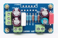
I bought the amplifier from Ebay named "AK-370", there is also a video where it is opened
Chip Amplifier AK-370
Attachments
Isn't what you want the same as Joe Rasmussen's been doing? https://www.diyaudio.com/community/...tt-transconductance-current-amplifier.239321/
Unfortunately it can't work with a bridge-tied load amplifier and it can't work when the feedback network is internal to the amplifier chip. Yours appears to be both of those things.Hello Marcel,
I need some hint: where would you wire from ground to feedback on this scheme with a resistor in between?
Can you draw it with MS paint and post it? Just in order to learn. Is it possible with this type of chip amp?
I bought the amplifier from Ebay named "AK-370", there is also a video where it is opened
Chip Amplifier AK-370
o.k. thank you for the feedback. I will see if I can build an amplifier like Rasmussen built it or I will try one of Merilainens LM350 Voltage Regulator amps.
Building an amplifier from the scratch takes some time. It would be nice to see some small amplifier already finished with just some correction of the internal wiring. This would spare a lot of time for making it.
Its a pity there are no commercial amplifiers available of the current drive type. Or does anyone know?
I tried Merilainens simple resistor method seems to work. I tried it here:
https://www.diyaudio.com/community/threads/new-15-full-range-fane.308652/post-7076903
With a high efficient loudspeaker (99db) you can waste some decibels of effciency just in order to try it out.
Did you have a look at rod elliott's page?
https://sound-au.com/articles/current-drive.htm
and
https://sound-au.com/project56.htm
https://sound-au.com/articles/current-drive.htm
and
https://sound-au.com/project56.htm
(quoted from first link)"Be very careful if you use IC power amps (LM3886 or TDA7293 for example). Most are designed to run at a particular minimum gain, and they may oscillate if the gain is reduced below the minimum recommended due to the current feedback. This is especially dangerous if the load impedance falls at high frequencies."
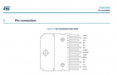
You chose the worst chipamp for that, as marcelvdg explains on post #8.Here is the pin connection, maybe it is more secure to know where to attach directly at the chip for wiring.
I would be grateful for a hint.
You don´t need a "commercial amplifiers available of the current drive type.", most do (except maybe for stability reasons) if you use the proper NFB network.
In general it´s easy to use the so called "mixed feedback" network, where you add a resistor from speaker "-" terminal to ground to sample current and send that signal to the NFB point, small problem is that it´s not "pure" current drive (hence the "mixed" label) because in general you still have an unavoidable NFB resistor to provide DC stability and avoid offset .... problem being that it also feeds back some AC/Audio.
Tell us which exact model speaker you will use, specially a link to it datasheet so we can see its impedance curve, and I´ll design an NFB network for you, to be used with a single ended amplifier chip (say LM1875), NOT a BTL tied one.
Output will be pure current drive, not horrible clunky putting a series resistor which to boot does NOT provide current drive, just something similar to mixed feedback at best.
Hello,Tell us which exact model speaker you will use, specially a link to it datasheet so we can see its impedance curve, and I´ll design an NFB network for you, to be used with a single ended amplifier chip (say LM1875), NOT a BTL tied one.
this is great.
I have a lot of loudspeakers. I only build fullrange loudspeakers with just one single driver and with dsp correction, so I do not care very much about the frequency response as it is with assisted measurements always made to be flat.
One of my next projects will be a Fane Sovereign 15-300TC in a small bass reflex box (60 Liters) tuned to 30 Hertz.
In the attachment you see the data sheet. It has its resonance frequency at approx. 50 Hertz.
But I use also:
Sica 12D - 12 inch fullrange driver from italy
L3401 a 12 inch fullrange driver brand "RFT" from former GDR - eastern germany
Small 8cm fullrange drivers from JVC
All drivers have treated diaphragms with aluminium foil a speciality of me:
https://www.diyaudio.com/community/threads/full-range-pics.87174/post-6711011
I saw Rod Elliots website - I enjoyed to read it but I did not find a buyable amplifier. But after a first rough look - maybe he sells PCBs for DIY projects. Do not know if there is a current driven amplifier PCB he offers.
I will also check out "MyRef Fremen" - will need some time to read this, seems to be very well discussed.
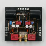
Makes it sense to buy this ready made gainclone with hard wiring from Ebay using LM1875? And find there the feedback point to work with the rewiring? (See attachment).
@JMFahey:
If there is a ready made commercial amplifier available where there is a description on how to modify the circuit to current drive just tell me.
For me it is great to get an overview about what exists and was done until now concerning availabilty of current drive amplifiers. I am grateful for all the links until now.
Attachments
Last edited:
If you get genuine lm3886, here is my mod:
https://www.diyaudio.com/community/threads/viral-projects-sort-of.351475/post-6410089
https://www.diyaudio.com/community/threads/viral-projects-sort-of.351475/post-6410089
Here you can see a dsp corrected 25cm fullrange loudspeaker. I used a Behringer Inuke Nu3000dsp amplifier for doing this.
https://www.diyaudio.com/community/...w-distortion-with-a-2-way.334757/post-6711184
However I am interested what an amplifier with current drive will achieve sonically - the distortion reduction and the compensation of the inductivity of the voice coil is interesting for me.
@adason
This looks very interesting.
Did I catch it correctly? You added just 220 ohms in between plus and minus of the loudspeaker output and you put 0,22 ohms into the minus output to the loudspeaker.
And you just lift off the leg of one resistor (feedback) and attach it in between the output-ohms?
This seems to be realizable even for me who is more into loudspeakers than electronics.
Easy mod!!
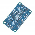
I saw on ebay the PCB from XY so it would be manageable.
I am also still interested in other designs.
https://www.diyaudio.com/community/...w-distortion-with-a-2-way.334757/post-6711184
However I am interested what an amplifier with current drive will achieve sonically - the distortion reduction and the compensation of the inductivity of the voice coil is interesting for me.
@adason
This looks very interesting.
Did I catch it correctly? You added just 220 ohms in between plus and minus of the loudspeaker output and you put 0,22 ohms into the minus output to the loudspeaker.
And you just lift off the leg of one resistor (feedback) and attach it in between the output-ohms?
This seems to be realizable even for me who is more into loudspeakers than electronics.
Easy mod!!
I saw on ebay the PCB from XY so it would be manageable.
I am also still interested in other designs.
Attachments
I would be grateful for a hint what to choose as electronics for a start as I am more into loudspeakers than electronics.Schematics would be very helpful, in any of those examples.
If you know a LM1875 board maybe preassembled where the schematic is existent for evaluation it is easier for me.
Like this? Sorry for awfull graphics, done on the phone...Schematics would be very helpful, in any of those examples.
Attachments
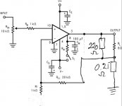
Thanks.Like this? Sorry for awfull graphics, done on the phone...
Much clearer than trying to imagine "in the air" through verbal explanations ... even in a relatively simple circuit such as 1875 uses.
It does work as intended (pure current drive), in principle, but with some side effects.
* original closed loop gain (the regular way to use it) has (20k/1k)+1=21X ... which is fine .
Since that amp can put out some 20W@8 ohm so some 12.6V RMS,its sensitivity is 12.6V/21=0.6V=600mV
Nice, comfortable, easy to drive.
* now if we add the "constant current NFB" network that way, we are adding its "gain" too .... more exactly "multiplying".
That network will give extra (8r/0.25r)+1=33X
Multiplying both we now have huge 21X*33X=693X
Sensitivity is now 12.6V/693=18mV
Might be good for some uses (direct microphone input? Rock Guitar amplifier?) but for ost uses,say after a preamp or almost any active Audio source it will be too much.
Besides, that gain also extends down to DC, so any minuscule offset turns into highish output offset.
* my starter suggestion (and that might be all that´s needed) is to short the 20k NFB resistor, and leave out the 1k one (it is shorted anyway by the 0.25 ohm one) so now we have 33X gain (which is manageable and comparable to "original" gain), reasonable sensitivity (12.6V/33X= 380 mV
And MOST important: now we have current drive .
Notes:
* there is still some power wasted in the 0.25 ohm resistor, but it´s nothing compared to, say, putting an 8 ohm one in series with speaker.
And which would still not be "current drive" but only "reduced damping"
- it may be refined better but for a quick simple solution it´s good enough.
- thanks to having an actual schematic to work with, a straightforward suggestion may be made ; otherwise we are never certain.
* I didn´t even mention the 220 ohm resistor since it´sway higher than any impedance an 8 ohm speaker can take, so we can safely ignore it and simplify Math. - one image is worth 1000 words DOES have some merit
")
Guess most follow the datasheet example.If you know a LM1875 board maybe preassembled where the schematic is existent for evaluation it is easier for me.
Adason apparently quoted part of it , so .... there´s your schematic.
- Home
- Amplifiers
- Chip Amps
- Chip amp modification to current drive