I hope so, too. We will see. I ordered in the far east.Wish you good luck, enough to get a working chip there.
Oh, I had a second look, its just the board, not assembled. So no chips or anything than the PCB included. The resistors and electrolytics I have at home but still no chips.
What was the price of the LM3866 before the "everlasting crisis" of chip production? Reichelt (traditional electronics dealer in germany) offers them for seven Euro a piece but they get them next year, they are out of stock. I am not prepared to pay 40-50 Dollar for a chip on Ebay.
D
Deleted member 375592
correct@mikets42
I am sorry to ask as I am not into electronics. The loudspeaker plus and minus is where the two zobel networks are?
WHY would you put a low value resistor (9.4 ohm for an 8 ohm speaker) in parallel with speaker in a system designed to current drive the speaker?my 2c: all you need is to ensure 3886 stability if you use DSP to EQ. I'd use 0.22 | 0.25 Ohm in series with spk; instead of a single 220 Ohm: {4.7 Ohm + 10uF} || {4.7 Ohm + 330nF} bypassing "4Ohm" spk. Double R / half C for 8 Ohm. The gain will be ~20dB, Ft~200kHz. Basically, you need to repeat gain/tau from figure 3 in the datasheet.
5uF + 9.4 ohm (your suggestion) means that speaker will practically halve its impedance at around 3300Hz so it will lose almost 6dB at that frequency, worsening as frequency goes up.
That speaker will sound duller than a blanket.
Even worse, its impedance at 10kHz is 12 ohm increasing treble, ... but now it will lose even more, the combination will be 5.7 ohm so treble loss will be over 6dB.
Making current drive meaningless.
This is the schematic of the STK4241mk2.
The current sensing 0.22 resistor is located at the output of the amplifier before the load.
If no load is connected, the amplifier remains stable.

Regards
Mike
The current sensing 0.22 resistor is located at the output of the amplifier before the load.
If no load is connected, the amplifier remains stable.
Regards
Mike
D
Deleted member 375592
You are correct. 5u was a typo. I meant 0.5u - for 4 Ohm spk, what is 0.25u for 8Ohm. so 3k3 -> 66kHz.WHY would you put a low value resistor (9.4 ohm for an 8 ohm speaker) in parallel with speaker in a system designed to current drive the speaker?
5uF + 9.4 ohm (your suggestion) means that speaker will practically halve its impedance at around 3300Hz so it will lose almost 6dB at that frequency, worsening as frequency goes up.
That speaker will sound duller than a blanket.
Even worse, its impedance at 10kHz is 12 ohm increasing treble, ... but now it will lose even more, the combination will be 5.7 ohm so treble loss will be over 6dB.
Making current drive meaningless.
@JMFahey
I am sorry. Reread it. Availability of the chip is important, too.
You asked me to specify a certain loudspeaker the amplifier will be used with. I answered that I only use fullrange drivers without classical crossovers. And named the Fane Sovereign 15-300tc and gave its specs in a pdf and how I will use it.
However I hope that a current amp is universally usable for a variety of fullrange loudspeakers. As I would always try a self made amplifier with cheap loudspeaker drivers first before attaching something expensive.
But we can stop here I will try to get my hands on some chips and will try out what was named until now.
It is nice to hear and see that there are designs out there using chip amps and which try to realize current drive. However it is a pity there is no current drive easily available on the market for ready use to the end consumer.
D
Deleted member 375592
I don't see how 0.22 senses anything. IMHO, it is a regular voltage drive with 40dB of gain.This is the schematic of the STK4241mk2.
The current sensing 0.22 resistor is located at the output of the amplifier before the load.
If no load is connected, the amplifier remains stable.
View attachment 1088795
Regards
Mike
I looked up the schematic - it was the unchanged voltage driven amplifier from the producer of the chip as far as I could see.I don't see how 0.22 senses anything. IMHO, it is a regular voltage drive with 40dB of gain.
The 0.22 ohm resistor between STK output and speaker not only does not increase output impedance or lower damping (same thing) but also "it isn´t even there" because voltage Negative Feedback is taken after it, output, as seen by speaker, is pure voltage only.
Amplifier behaves like a pure voltage generator.
On the contrary , if we put exact same 0.22 ohm resistor between speaker return and ground, and take NFB from there, amplifier will still keep such output voltage stable , independent from load, that´s what voltage NFB does, BUT now it will be constant across the 0.22 ohm resistor ONLY, independent from what the speaker itself drops,so for the speaker, amp will behave like a constant current source.
Which is what we wanted.
Not difficult, definitely not "magic", once you understand how it works, it "clicks" in your mind.
That´s why I said earlier: you don´t need to hunt for a specific constant current chipamp, ANY one can be made to work so, by proper choice of NFB network.
FWIW, I have developed my own kind of mixed feedback for Guitar Amp use since 1972 when for reasons of force majeure tubes disappeared from Argentine market (like everything else which was imported) because we got into default, and I switched from making tube Fender clones to SS, this was one way to recover some of the "Tube feel"
I was in 4th year Engineering at the moment, starting to study Op Amps, and solution was self-evident, once you know the basics.
Amplifier behaves like a pure voltage generator.
On the contrary , if we put exact same 0.22 ohm resistor between speaker return and ground, and take NFB from there, amplifier will still keep such output voltage stable , independent from load, that´s what voltage NFB does, BUT now it will be constant across the 0.22 ohm resistor ONLY, independent from what the speaker itself drops,so for the speaker, amp will behave like a constant current source.
Which is what we wanted.
Not difficult, definitely not "magic", once you understand how it works, it "clicks" in your mind.
That´s why I said earlier: you don´t need to hunt for a specific constant current chipamp, ANY one can be made to work so, by proper choice of NFB network.
FWIW, I have developed my own kind of mixed feedback for Guitar Amp use since 1972
when for reasons of force majeure tubes disappeared from Argentine market (like everything else which was imported) because we got into default, and I switched from making tube Fender clones to SS, this was one way to recover some of the "Tube feel"I was in 4th year Engineering at the moment, starting to study Op Amps, and solution was self-evident, once you know the basics.

Thanks for the explanation.
I've amended the schematic for the current drive mod.
I think this is what you're referring to.

I've amended the schematic for the current drive mod.
I think this is what you're referring to.
Since you are taking 0.22/8.22 of the output voltage, R9 should probably be dropped from 56k to 1.5k.I think this is what you're referring to.
IAC, C15 has to be driven from the chip, not the 0.22r.
Two available here unless they've soldI hope so, too. We will see. I ordered in the far east.
Oh, I had a second look, its just the board, not assembled. So no chips or anything than the PCB included. The resistors and electrolytics I have at home but still no chips.
What was the price of the LM3866 before the "everlasting crisis" of chip production? Reichelt (traditional electronics dealer in germany) offers them for seven Euro a piece but they get them next year, they are out of stock. I am not prepared to pay 40-50 Dollar for a chip on Ebay.
Almost there but still a couple errors.Thanks for the explanation.
I've amended the schematic for the current drive mod.
I think this is what you're referring to.
View attachment 1088872
Too sleepy now, will edit and repost your schematic when I wake up.
Here, this is the proper way.
* you keep DC NFB , DC unity gin (so minimized offset)
* you have 100% current drive
* Now current into speaker is Vin/0.22 ohm
* Gain is RL/0.22 ohm
* Have been using this in my Guitar amps since 1972
Musicians call them "bold, brash, aggressive" or "Fahey amps have bite"

Simple, huh? 😉
* you keep DC NFB , DC unity gin (so minimized offset)
* you have 100% current drive
* Now current into speaker is Vin/0.22 ohm
* Gain is RL/0.22 ohm
* Have been using this in my Guitar amps since 1972
Musicians call them "bold, brash, aggressive" or "Fahey amps have bite"
Simple, huh? 😉
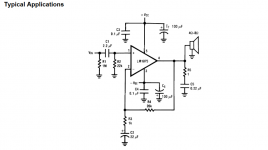
That is really simple, like it. AND the chip is commonly available.
However, is there a parts list? I can not read well all the values. Like C3, L1, R22.
However, is there a parts list? I can not read well all the values. Like C3, L1, R22.
- Home
- Amplifiers
- Chip Amps
- Chip amp modification to current drive