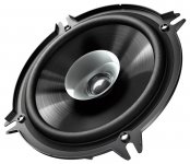
The fullrange driver is a
It has a stiffer polypropylene double cone. This kind of cone would have been considered "High End" in the 80ies.
In a listening test it showed really good sonics and measurements also looked acceptable.
However the driver has a pretty standard driving system as there is no copper / faraday ring used. It means the impedance of the voice coil could be lower for better high frequency reproduction and the distortion could be less I am really glad to see and hear if the distortion goes down and bass and high tones will be accentuated.
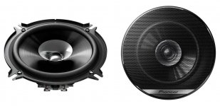
Pioneer TS-G1310F
out of actual production.It has a stiffer polypropylene double cone. This kind of cone would have been considered "High End" in the 80ies.
In a listening test it showed really good sonics and measurements also looked acceptable.
However the driver has a pretty standard driving system as there is no copper / faraday ring used. It means the impedance of the voice coil could be lower for better high frequency reproduction and the distortion could be less I am really glad to see and hear if the distortion goes down and bass and high tones will be accentuated.
Attachments
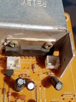
thermal conductivity of marble is 2,8 W/mKwill use a piece of marble the TDAs glued onto it. Is this functional?
thermal conductivity of aluminium: 236 W/mK
I would say: no, it is not functional, as it has just 1% of thermal conductivity, that you need to get the heat from the small chip surface area to the entire mass of the heat sink.
it may, however be better to use marble than nothing at all and could be ok for testing without any load.
also keep in mind the TDA2003 is a very old part that was never intended for high quality reproduction, but for car radios. however it may be a good rugged chip for experimentation - so keep going!
o.k. I will look out for some real heatsink. Is there no stone which has acceptable thermal conductivity?thermal conductivity of marble is 2,8 W/mK
thermal conductivity of aluminium: 236 W/mK
I would say: no, it is not functional, as it has just 1% of thermal conductivity, that you need to get the heat from the small chip surface area to the entire mass of the heat sink.
it may, however be better to use marble than nothing at all and could be ok for testing without any load.
also keep in mind the TDA2003 is a very old part that was never intended for high quality reproduction, but for car radios. however it may be a good rugged chip for experimentation - so keep going!
Yes the TDA 2003 is not high end chip but the distortion is happening on the loudspeakers side much more than in the electronics. Any relevant distortion reduction will be of benefit. Much more than a chip amp having 0,01 per cent of distortion than 0,1 per cent of distortion.
As long distortion in loudspeakers is measured in several per cents - especially with cheaper loudspeaker drivers - the benefit of a functioning current feedback will pay off.
not really, apart from very expensive ones (diamond or other crystal structures).Is there no stone which has acceptable thermal conductivity?
have a look:
https://de.wikipedia.org/wiki/Wärmeleitfähigkeit#Beispielwerte (german)
https://en.wikipedia.org/wiki/List_of_thermal_conductivities (english)
Don´t feed the troll 😉thermal conductivity of marble is 2,8 W/mK
thermal conductivity of aluminium: 236 W/mK
Excellent approach without PCB. Check out also this threads in this case:Hello,
this is great.
I have a lot of loudspeakers. I only build fullrange loudspeakers with just one single driver and with dsp correction, so I do not care very much about the frequency response as it is with assisted measurements always made to be flat.
One of my next projects will be a Fane Sovereign 15-300TC in a small bass reflex box (60 Liters) tuned to 30 Hertz.
In the attachment you see the data sheet. It has its resonance frequency at approx. 50 Hertz.
But I use also:
Sica 12D - 12 inch fullrange driver from italy
L3401 a 12 inch fullrange driver brand "RFT" from former GDR - eastern germany
Small 8cm fullrange drivers from JVC
All drivers have treated diaphragms with aluminium foil a speciality of me:
https://www.diyaudio.com/community/threads/full-range-pics.87174/post-6711011
I saw Rod Elliots website - I enjoyed to read it but I did not find a buyable amplifier. But after a first rough look - maybe he sells PCBs for DIY projects. Do not know if there is a current driven amplifier PCB he offers.
I will also check out "MyRef Fremen" - will need some time to read this, seems to be very well discussed.
Makes it sense to buy this ready made gainclone with hard wiring from Ebay using LM1875? And find there the feedback point to work with the rewiring? (See attachment).
@JMFahey:
If there is a ready made commercial amplifier available where there is a description on how to modify the circuit to current drive just tell me.
For me it is great to get an overview about what exists and was done until now concerning availabilty of current drive amplifiers. I am grateful for all the links until now.
https://www.diyaudio.com/community/...b-for-tda7293-tda7294-tda7295-tda7296.223201/
https://www.diyaudio.com/community/threads/lm3886-pcb-vs-point-to-point-with-data.252436/
https://www.diyaudio.com/community/threads/optimizing-tda7294-output.226437/page-24 (#473)
https://www.diyaudio.com/community/...-tda7293-tda7294-lm3886-etc-available.222793/
Are there any benefits by use of current drive, when the impedance plot of the loudspeaker is flat (i. e. like a normal resistor of 6-8 ohms - that is done by use of RC/RCL network to equalize the increasing impedance through voice coil inductance and the impedance maximum around fo) ??
Without impedance equalizing the audible differences on full range drivers between current drive and voltage drive are significant due large impedance fluctuations.
Last edited:

Are there any benefits by use of current drive, when the impedance plot of the loudspeaker is flat (i. e. like a normal resistor of 6-8 ohms - that is done by use of RC/RCL network to equalize the increasing impedance through voice coil inductance and the impedance maximum around fo) ??
Without impedance equalizing the audible differences on full range drivers between current drive and voltage drive are significant due large impedance fluctuations.
I use MiniDsp or Behringer DEQ2496 or Smartfone with EQ App for correcting ANY loudspeaker.
I want to try out current drive/current feedback in order to find out how much it does. If it works I would need less or no EQ with appropriate fullrange drivers - impedance correction is not needed if I design the loudspeaker by myself controlling all parameters.
It would be great if distortion really goes down. I have a hint for this by trying out the simple resistor method of Esa Merilainen (website about current drive).
It works with simple resistors. I will make sound recordings and measurements before and after modification with resistor or current feedback.
There are measurements from Nelson Pass on this topic
https://www.passdiy.com/project/amp...e-amplifiers-and-sensitive-full-range-drivers
https://www.passdiy.com/project/amp...e-amplifiers-and-sensitive-full-range-drivers
I was making a new schematic in order to plan how to hard wire the handfull of parts I need to make the "current feedback" amplifier with the TDA2003 amplifier as far as this is possible with a 2D schematic.
Does anyone know if I can use one SMPS for left an right channel (two TDA2003) concerning hum or noise? Or would it be better to use two SMPS besides the fact that I would have more power headroom with two SMPS (=separated power supply for each channel)?
Can I wire to the 12 Volt SMPS also the preamp (which has its own LM7805 to generate the 5 Volts it needs) - or is this not good concerning hum or noise?
Is a simple star grounding enough or shall I separate a little bit the power section from the input section? (Although I did not really understand why only some centimeters of separation on the ground shall help anything concerning noise and hum).
Attachments
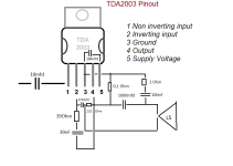
Yes you can power the preamp out of the same main 12V supply,doubly so if it has its own regulator.
You must be careful with grounding, but that applies everyhere.
What scratches me backwards is having a meager 5V supply for the preamp,what kind of signal can it put out?
Please post a direct link to it.
You must be careful with grounding, but that applies everyhere.
What scratches me backwards is having a meager 5V supply for the preamp,what kind of signal can it put out?
Please post a direct link to it.
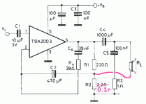
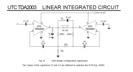
As I am not into electronics, what prevents BTL configuration being used with current feedback?
Why does the bridged amp not need the output capacitor of 1000mfd? Is there no DC in this configuration on the output?
In the proposed current feedback schematic there is a 0,1 Ohm resistor instead of 2,2 Ohms - does this low resistance not prevent to let the electricity flow to the loudspeaker which has a higher impedance?
Attachments
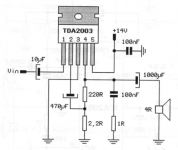
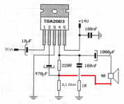
Ah, I understand now, the 0,1 Ohm is shorted to the ground and the loudspeaker gets its energy from 4 and 3.
I like the description on this website of each electronic part used:
https://www.eleccircuit.com/hi-fi-audio-amplifier-by-ic-tda2003/
Website with explanation
https://www.eleccircuit.com/hi-fi-audio-amplifier-by-ic-tda2003/
Website with explanation
The .1R is in series with the loudspeaker load, not in parallel, so the current flowing through it will be approximately the same as what's traveling through the speaker. .1R is better than 2R because the feedback is set up to put a fixed current through the resistor (and thus the speaker). The higher resistance, the more power is wasted in the resistor (and a higher power resistor is necessary).
The .1R is in series with the loudspeaker load, not in parallel, so the current flowing through it will be approximately the same as what's traveling through the speaker. .1R is better than 2R because the feedback is set up to put a fixed current through the resistor (and thus the speaker). The higher resistance, the more power is wasted in the resistor (and a higher power resistor is necessary).
Is the 0,1 Ohm resistor setting the gain? I read that the 220 Ohms together with the 2.2 Ohms are setting the gain in the standard schematic for the TDA2003.
I appreciate 0,1 Ohms because the amp does not have much watts - and it should not be wasted.
- Home
- Amplifiers
- Chip Amps
- Chip amp modification to current drive