In the datasheet they recommend +/-23 VDC for this amplifier.
+/-20-21 VDC is almost the same when using 15-0-15 Trafo.
+/-20-21 VDC is almost the same when using 15-0-15 Trafo.
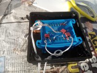
Now I found some time to modify STK4132 amplifier.
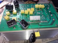
I did put 1mfd foils on every electrolytic. Cut the trace from ground to the - of the speaker binding posts.
The 100mfd 16v feedback cap changed to 220mfd bipolar, 25v and wired them to the speaker output minus.
Wired current sensing resistance 0.22 ohms, 3 watts to the combined ground of the speaker out.
I left the 4558 op amp in place as I have no desoldering copper at hand.
Think about putting a holder so I can try some other op amp. Got NE5532 and LM4562 for experiments.
Images before modification:
https://www.diyaudio.com/community/...fication-to-current-drive.389985/post-7274732
Prepared 15 0 15 transformer, 25VA.
I bought a 15 0 15 transformer with 120va as well. Want to try out if it makes a difference.
Images of schematic in post #169
Attachments
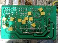

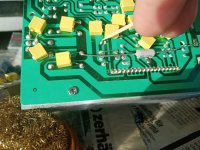
Correction for the points where to solder the feedback cap after removing old 100mfd 16v.
560 ohms is on this pre-assembled Chinese board before the feedback cap.
The 560 ohms to ground are R14 and R20 you can put the cap directly to one of their legs or you must bridge these R's.
560 ohms is on this pre-assembled Chinese board before the feedback cap.
The 560 ohms to ground are R14 and R20 you can put the cap directly to one of their legs or you must bridge these R's.
Attachments
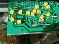
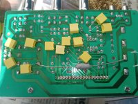
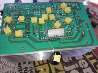
Looked at the schematic and the PCB.
Do not see local decoupling for the chip.
So added 4.7nanofarad foil. 1mfd MKT foil and 680mfd electrolytic directly to the pins 3 and 12 of the STK4132 chip.
I prepared a second amp left original but tweaked with foils in order to compare the sound of both amps. The current driven with a voltage driven amp.
Attachments
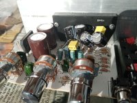
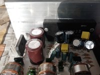
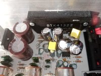
The second amp had 2200 mfd in the power supply, the other had 3900 mfd.
So I added extra capacitors to make a comparison possible.
At these cheapo amps the manufacturers "throw" what they can get.
So I added extra capacitors to make a comparison possible.
At these cheapo amps the manufacturers "throw" what they can get.
I first understood 1 mF (millifarad = 1000 uF) - just for your information: use correct prefixes if you want to avoid misunderstandings!1mfd foils
(Edit: I apologize for using the wrong prefix myself ... it should of course be µF)
Thank for this information. As I do not know how to write it I will use "microfarad". That will be clear
Read about the 4558 Op amp on this forum. There is one on the STK4132 board for the tone controls.
I was thinking about changing this op amp from the beginning seventies.
Found that experienced DIY users mentioned that its already an audio grade op amp and that not always a change will bring a sonic profit.
Some users who did the work to change these op amps for "better" ones did not hear any difference or made the sound worse.
I think I will leave it as is.
I expect the STK will sound better than the TDA2004 boards (Better specs and no output capacitor). However the main sonical progress lies in the modification of the amps to current drive and the dominant drop in distortion.
The STK4132 is rated at 0,3% THD. Loudspeakers have much more distortion and a drop of 10-20db in distortion on the loudspeakers changes the sound dramatically. The amplifier is not the limiting factor here.
It seems that current drive changes not only the distortion, the frequency response in the bass and the highs but also impulse response because fullrange drivers with faraday /copper ring on the pole piece had a profit in the bass region which sounds more right and convincing than with voltage drive.
The mids profit, too:
As distortion is mostly perceptible in the mid frequencies by the ear they sound much better under current drive. Psychoacoustically the distortion in the mid frequencies add a monotony to the sound. Without this distortion highs and bass are better perceptible.
Interesting is that the frequency linearization due to current drive works so well that I do not feel the necessity any more for correcting the response of my fullrange drivers without crossover network with digital signal processing (dsp).
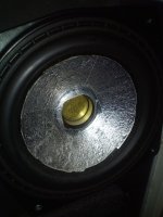
Here copper rings DIY added to existing driver. This helps already bringing distortion down. These drivers still profit from current drive.


I was thinking about changing this op amp from the beginning seventies.
Found that experienced DIY users mentioned that its already an audio grade op amp and that not always a change will bring a sonic profit.
Some users who did the work to change these op amps for "better" ones did not hear any difference or made the sound worse.
I think I will leave it as is.
I expect the STK will sound better than the TDA2004 boards (Better specs and no output capacitor). However the main sonical progress lies in the modification of the amps to current drive and the dominant drop in distortion.
The STK4132 is rated at 0,3% THD. Loudspeakers have much more distortion and a drop of 10-20db in distortion on the loudspeakers changes the sound dramatically. The amplifier is not the limiting factor here.
It seems that current drive changes not only the distortion, the frequency response in the bass and the highs but also impulse response because fullrange drivers with faraday /copper ring on the pole piece had a profit in the bass region which sounds more right and convincing than with voltage drive.
The mids profit, too:
As distortion is mostly perceptible in the mid frequencies by the ear they sound much better under current drive. Psychoacoustically the distortion in the mid frequencies add a monotony to the sound. Without this distortion highs and bass are better perceptible.
Interesting is that the frequency linearization due to current drive works so well that I do not feel the necessity any more for correcting the response of my fullrange drivers without crossover network with digital signal processing (dsp).
Here copper rings DIY added to existing driver. This helps already bringing distortion down. These drivers still profit from current drive.
Attachments
Now soldered one LM1875 board to basic current feedback.
From pin two 340 mikrofarad to minus of the speaker. 0,22 ohm, 3 watts to ground.
Foils for the input and 3.3 mikrofarad MKP directly on the chip on legs 3 and 5 for decoupling the power.
One capacitor of 47 mikrofarad removed to cut the trace from pin 2 to ground.


From pin two 340 mikrofarad to minus of the speaker. 0,22 ohm, 3 watts to ground.
Foils for the input and 3.3 mikrofarad MKP directly on the chip on legs 3 and 5 for decoupling the power.
One capacitor of 47 mikrofarad removed to cut the trace from pin 2 to ground.
Correction for post #173 in this thread (conversion of TDA2003 to current drive).
JMFahey checked the schematics I made.
.jpg")
C4 and C6 have to be connected to ground. Schematic has to be corrected for this.
JMFahey checked the schematics I made.
C4 and C6 have to be connected to ground. Schematic has to be corrected for this.
@Freedom666
Here is a complete circuit with LM1875 Current Drive.
Most is like you already have suggested.
But the important change is R2+C5 is connected to Ground.
This gives much better frequency performance.

Here is a complete circuit with LM1875 Current Drive.
Most is like you already have suggested.
But the important change is R2+C5 is connected to Ground.
This gives much better frequency performance.
Connection R2, C5 to ground I will check this.
It seems very simple work I do transforming these amps to current feedback. Maybe annoying to professionals.
But you have to study the board in order to find out the right wiring. In order to make no faults.
It seems very simple work I do transforming these amps to current feedback. Maybe annoying to professionals.
But you have to study the board in order to find out the right wiring. In order to make no faults.
Using Esa Merilainens simple resistor method, example for using a little bit of current drive:
https://www.diyaudio.com/community/threads/loudspeaker-for-current-drive.403936/post-7479266

https://www.diyaudio.com/community/threads/loudspeaker-for-current-drive.403936/post-7479266
- Home
- Amplifiers
- Chip Amps
- Chip amp modification to current drive