The DC voltage at the output should be somewhere around half the supply voltage. C4 ensures that doesn't cause a large DC current through the loudspeaker.
In a bridge-tied load configuration, both sides of the loudspeaker are at essentially the same DC bias voltage, so there is no big DC voltage across the loudspeaker anyway.
In a bridge-tied load configuration, both sides of the loudspeaker are at essentially the same DC bias voltage, so there is no big DC voltage across the loudspeaker anyway.

Is the 0,1 Ohm resistor setting the gain?
Yes. The voltage to current gain is ideally 1/(0.1 ohm) = 10 S where S stands for siemens, also known as A/V or mho.
I read that the 220 Ohms together with the 2.2 Ohms are setting the gain in the standard schematic for the TDA2003.
This isn't the standard schematic.
I appreciate 0,1 Ohms because the amp does not have much watts - and it should not be wasted.
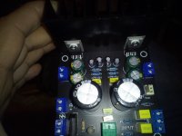
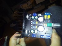
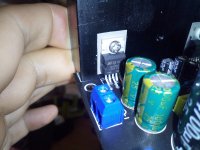
I bought this ready assembled stereo amplifier module with input and heatsinking.
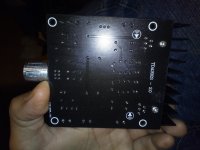
Now I am checking the circuitry and the values. It seems to be a three layer pcb as I can not see on both sides all the tracking of signals.
I found out that it should be the standard circuitry from the datasheet.
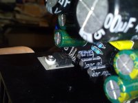
The 470mfd is here 220mfd. Input capacitor is 2,2mfd instead of 10mfd.
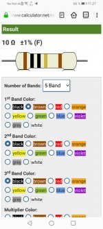
The three resistors are from top to bottom 41 ohm (yellow, brown, black, gold, brown, instead of 39 ohms), the next is 220 ohms (red, red, black, black, brown) and the last is 10 ohms due to the resistor colour calculator hope I read this one well, the colour on the rings are brown, gold, black, black, brown.
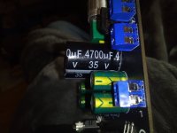
My question: as I can identify the 220mfd capacitance. Can I wire here the minus of the loudspeaker (omitting the ground on the pcb for the loudspeaker).
That should do it?!
I will leave the other canal unchanged for having the possibility to check the sound difference.
Now I am checking the circuitry and the values. It seems to be a three layer pcb as I can not see on both sides all the tracking of signals.
I found out that it should be the standard circuitry from the datasheet.
The 470mfd is here 220mfd. Input capacitor is 2,2mfd instead of 10mfd.
The three resistors are from top to bottom 41 ohm (yellow, brown, black, gold, brown, instead of 39 ohms), the next is 220 ohms (red, red, black, black, brown) and the last is 10 ohms due to the resistor colour calculator hope I read this one well, the colour on the rings are brown, gold, black, black, brown.
My question: as I can identify the 220mfd capacitance. Can I wire here the minus of the loudspeaker (omitting the ground on the pcb for the loudspeaker).
That should do it?!
I will leave the other canal unchanged for having the possibility to check the sound difference.
Attachments
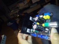
I would wire the minus of the speaker to minus of the 220mfd and the plus of the loudspeaker to the prepared plus on the pcb for the loudspeaker

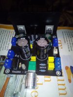
As a preamp I would use my smartfone with an opened connection cable so I can screw the cable to the pcb.
I will now wire the amplifier up in original condition the see if it works.
I will now wire the amplifier up in original condition the see if it works.
Amplifier works. Both channels ok.
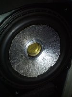
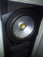
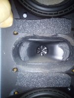
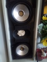
Image of 12cm fullrange driver both sides with aluminium foil removed dustcap and a 50 cent Euro piece glued to the pole piece. This helps bringing down the impedance of the voice coil and minimizes audibly the distortion.
The 50 cent euro coin contains some copper so it works as a faraday ring.
Its a two driver arrangement and a piezo tweeter with crossover and aluminium treated diaphragm, too.
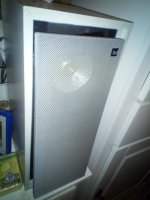
The box is an old DUAL loudspeaker from germany.
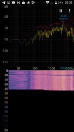
The speaker is linear from 100 Hertz to 20khz with some extra highs beyond 5khz due to the piezo horn tweeter.
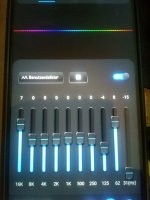
With active EQ it does a bit more in the bass. For this I use the EQ in the mediaplayer of my smartfone.
Image of 12cm fullrange driver both sides with aluminium foil removed dustcap and a 50 cent Euro piece glued to the pole piece. This helps bringing down the impedance of the voice coil and minimizes audibly the distortion.
The 50 cent euro coin contains some copper so it works as a faraday ring.
Its a two driver arrangement and a piezo tweeter with crossover and aluminium treated diaphragm, too.
The box is an old DUAL loudspeaker from germany.
The speaker is linear from 100 Hertz to 20khz with some extra highs beyond 5khz due to the piezo horn tweeter.
With active EQ it does a bit more in the bass. For this I use the EQ in the mediaplayer of my smartfone.
Attachments


I must state that this loudspeaker is not the best candidate for testing the distortion reduction due to current feedback as I added a Faraday ring to the pole piece which brought distortion quite down. The speaker sounds pretty high end already. Current drive/feedback helps most simple speakers to sound better. The contrast will be audible but it will not be overwhelming with my Dual clone speakers.
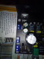
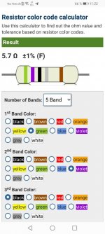
Ok I reread the resistors with the help of a camera. Not easy to detect the colours correctly.
However R2 is a highish 5.7 ohms. Must be changed to 0.1 ohms.
Cx and Rx are on this board 100nf and 10 ohms.
C3 is missing, they only have 2,2 mfd close to pin 5 and 3.
However R2 is a highish 5.7 ohms. Must be changed to 0.1 ohms.
Cx and Rx are on this board 100nf and 10 ohms.
C3 is missing, they only have 2,2 mfd close to pin 5 and 3.
Attachments


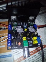
The only sound bottleneck is C4 as this is not a bipolar type. Not quite audio. Will put some Wima MKS of 10 mfd in parallel or change for a bipolar 3300 mfd composed of two 6800mfd in series with the grounds connected together.
I have ordered 0,1 Ohm resistors. Just to finish the current feedback amplifier with TDA2003.
I have a question - is it possible to make a current driven amplifier with the ICs LM13700 or LT1228?
Is it possible to use many of them in parallel (like I heard from NE5532 in some project) for more power?
Or is it possible to amplify the outcoming signal of one chip with some simple circuit - just providing more power?
Here more information:
https://en.wikipedia.org/wiki/LM13700
https://www.analog.com/en/products/lt1228.html#product-tools
Attachments
- Home
- Amplifiers
- Chip Amps
- Chip amp modification to current drive