These are the latest measured results after a number of modifications. Unfortunately did not save measurements from before, but they were around -105dB distortion if I remember correctly.
Now, I will try to find a solution for the noise. Not that it is audible, but for the heck of it. I hope to post pictures before and after.
Now, I will try to find a solution for the noise. Not that it is audible, but for the heck of it. I hope to post pictures before and after.
Thanks for the update...
Looking forward to see the progress and updated parts.
Great job on distortion..
Looking forward to see the progress and updated parts.
Great job on distortion..
Last edited:

So, as you can see, distortion is pretty good. However, noise isn't, as the following measurement shows.

We can see two things in this measurement. The first is that as a percentage, noise is more than 10 times higher than distortion. Since distortion is extremely low, that in itself is nothing to worry about, but it ain't right. The second thing that is visible are the sidebands around the 700 Hz central peaks, which are exactly 100 Hz right and left from the central peak. This is indicative of amplitude modulation, and not very nice to have. As to audibility, it is at an extremely low level, but it just should not be there.
As soon as RS delivers (which should be today, but one knever knows) I will make a slight adaption in the decoupling of the AK4497, which I think is responsible for this. That should also bring the noise level down.
Pfeww lucky to have you on board for this board...[emoji6].
So the board is allready good out of the box. But with your mods.... It can be very very good.
So the board is allready good out of the box. But with your mods.... It can be very very good.
< -120dB distortion from a 200 USD DAC!
The more I have worked with this board, the more I am amazed at the untapped potential it contains. Look at these two measurements.
Headlines: 0.000056% THD, 0.00074% THD+N @ 1 kHz. I want the noise down further, but it is uncased right now, so that might make some difference.
<-120dB distortion from a 200 USD board!

I found the cause for the AM-modulation that was made visible in the former FFT, and it is gone. The board contains one major error, as well as a number of other shortcomings, more about that later. But first another measurement showing distortion versus frequency.

Now for dinner and later some improvement hints.
The more I have worked with this board, the more I am amazed at the untapped potential it contains. Look at these two measurements.
Headlines: 0.000056% THD, 0.00074% THD+N @ 1 kHz. I want the noise down further, but it is uncased right now, so that might make some difference.
<-120dB distortion from a 200 USD board!
I found the cause for the AM-modulation that was made visible in the former FFT, and it is gone. The board contains one major error, as well as a number of other shortcomings, more about that later. But first another measurement showing distortion versus frequency.
Now for dinner and later some improvement hints.

This modification is almost mandatory. The 1 uF coupling cap from the digital section is too small to drive the 10k resistor to ground on the analog side; 3dB point around 15 Hz. AKM recommends 100 uF coupling caps. I used 220 uF because I had them laying around. Adding these makes a large measurable difference and also make the bass sound a lot tighter.

The coupling cap runs into a Sallen-Key connected opamp. AKM recommends a second order low pass filter with f3dB around 180 kHz. The values chosen on the board as it comes deliver a filter with a much higher corner frequency. I calculated the proper values for the SK-filter, but for reasons I don't want to spend time on, this created high DC-offsets. Therefore the solution chosen is to split the second order low pass in two. This here creates the first pole. 120 Ohm drive 10 nF for the required corner frequency.
This mod is equally recommended.

Below the opamp, proper decoupling close to the pins.
Easy to do and every little bit helps.
Attachments
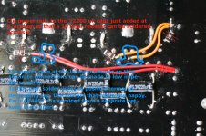
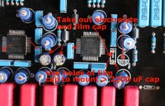
The other two pictures show a lay out error that has to be corrected as per instructions. The smal 47 uF needs to be replaced by something much bigger - 2200uF according to AKM. This lay out/ parts error in all likelihood caused the AM modulation.
In order to create the second pole in the filter, solder a 100nF COG across the active pins of the XLR to ground. Together with the 100 Hz output resistor, this brings us were we want to be.
Opamp used are OPA1612.
There is no reason to use a second opamp to drive the RCA output, it can only deteriorate sound. Therefore, the second opamp is ausradiert, see pictures.
It now measures better THD-wise than the published specs for OPA134 🙂
Last edited:
What I don't like is that at the low end, distortion has slightly increased after the changes. I will look at it tomorrow.
Improve it till it no longer works!
Improve it till it no longer works!
what about the exposed pad of the ak4497- it is connected at all? There are similar boards sold at aliexpress without the chip. They show the area beneath the chip totally coated.
and solder splatters all around! brrrr...200 USD board!
what about the exposed pad of the ak4497- it is connected at all? There are similar boards sold at aliexpress without the chip. They show the area beneath the chip totally coated.
and solder splatters all around! brrrr...
The board was really nice and clean when I got it. The muck is from all the rework and will be cleaned tomorrow. Chip appears to be mounted correctly, as is also evidenced by the results. I bought the board with the chip mounted.
thank you, I was thinking about something like this. It seems to be a generic design used by several vendors:
AK4497 HIFI AUDIO USB DAC decoder board (without AK4497 chip) AK4118 NE5534 DIY power amplifier board support DOP DSD-in Amplifier from Consumer Electronics on Aliexpress.com | Alibaba Group
since they obviously lacquered the area during pcb production, how could the humble buyer with pre soldered chip be certain if the pad is connected or or not?
Thanks Vacuphile,
That's a nice write up.... The board is not in yet.
And i guess i have to sleep a night or two to do those mods... I would like to though.
The first picture looks simple to do... The others looks more challenging.
But it can be more simple when i have a vision on the board.
The Red text with the resistors those are replaced with the mentioned values?
And the SK opamp is not necessary I understand?
Thanks again.
Last edited:
Also considered that board but they discouraged me that one because of the Xmos daughter card which is not stable.thank you, I was thinking about something like this. It seems to be a generic design used by several vendors:
AK4497 HIFI AUDIO USB DAC decoder board (without AK4497 chip) AK4118 NE5534 DIY power amplifier board support DOP DSD-in Amplifier from Consumer Electronics on Aliexpress.com | Alibaba Group
since they obviously lacquered the area during pcb production, how could the humble buyer with pre soldered chip be certain if the pad is connected or or not?
As you can see the USB connection is on the board.
In the black board you can choose your own card.
Finally mine arrived this weekend... Hooked it up with a u208 card.
It's playing but the sample rate is not displayed on the screen.??
Familiar?
I have hooked up the six header pins... But Spdif is going nowhere?
I see a pcb solder hole beneath the header pin. Is that the Spdif connection?
All the connector holes are marked except that one.
It's playing but the sample rate is not displayed on the screen.??
Familiar?
I have hooked up the six header pins... But Spdif is going nowhere?
I see a pcb solder hole beneath the header pin. Is that the Spdif connection?
All the connector holes are marked except that one.
Last edited:
Okay... So that hole is not for Spdif? Looked up in the AKM4118 pins.Yes, same here,
Have fun!
Looks like it's going IPS0 and RX4?
Thought maybe spdif will gives the signal.
When i unplug usb its says DSD?
Kind of sucks the information is not displayed.
- Home
- Source & Line
- Digital Line Level
- Chinese AK4497 DAC dual-chip decoder board