Hi Mark.
Cool. Thank you so much for the detailed explanation and the guidance.
Parts have been ordered tonight and the plan is to use the breadboard layout you have described somewhat earlier in this thread.
I keep you posted on my success and possible results with the Amplimo.
BR
Cool. Thank you so much for the detailed explanation and the guidance.
Parts have been ordered tonight and the plan is to use the breadboard layout you have described somewhat earlier in this thread.
I keep you posted on my success and possible results with the Amplimo.
BR
Ding dong ... or not quite but almost.
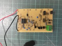
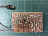
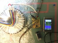
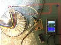
Last night I had some time to throw together the Cheapomodo. Took about 3hours. However as the evening drew to an end I had no time checking it before hooking it up to the transformer. I hope I did everything ok and will double check tonight. Attached you can find some pics so if you see a major hiccup please let me know.
I thought I had read somewhere a post from Mark on how to check the thing before going hot but I simply can’t find it anymore. A hint would be appreciated.
Attachments
Last edited:
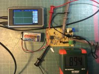
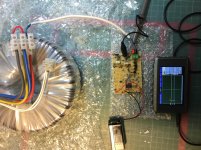
Oh I am in trouble. It doesn’t work. Nothing. See pic below. I would have expected to see something on the scope channel which connects to the drain pin. Nothing.
I double checked all the connections and resistor values. Also measured with the diode test mode the Mosfets from source to drain and got ca .7v. Opposite direction ca 1.4v.
What am I doing wrong? Wrong MOSFET? Wrong PNP Transistor? Wrong SE555? Fried components? How can I find out as this is out of my league.
Thanks. Really appreciate any help.
Attachments
Last edited:
What am I doing wrong? Wrong MOSFET? Wrong PNP Transistor? Wrong SE555? Fried components? How can I find out as this is out of my league.
Thanks. Really appreciate any help.
Probe with the scope leg 3 of the 555 chip, see if you get a square wave output...
If not, look for a hookup error. fix it and move to the next stage for validation of the signal, and so on to the last stage.
Good luck....
Thanks to the two of you. I certainly got the square wave on leg 3 alright.
Mark am I understanding your post correctly. I need to switch the pins of the PNP? Well, testing the unmounted pnp with a multimeter confirmed the change in the data sheet. Base is indeed the 3rd leg.
Do you think the wrong current installation caused some harm to the rest of the circuit?
Again thx a lot for your help and time.
Last edited:
I think I did it. Switch the PNPs pins according to the data sheet of the BC636 with 1 being Emitter, 2 Collector and 3 Base, which differs from the originally used PNP.
Please find attached the scope curves with yellow resembling the output while using Cx 10nF, Cs 150nF and the resistor disconnected. Timebase 1ms/div. Blue is the signal taken from the drain pin of the mosfet.
What do you think does that look ok?
No time today to hook up a transformer. Got to go shopping early tomorrow morning with the wife.
Attachments

So guys. Here are my results on a 800VA, 230v prim. , 2x25v sec. Amplimo toroid.
Cx10nF, Cs150nF, Rs10ohm seems to dampen the ringing.
With Rs infinite the ringing is at approx 1Mhz. In this case the primaries and the secondaries were shortened. It did make a difference though if both the secondaries were connected via the center conductor.
Scope: 500mV/div, 500nS/div.
Cx10nF, Cs150nF, Rs10ohm seems to dampen the ringing.
With Rs infinite the ringing is at approx 1Mhz. In this case the primaries and the secondaries were shortened. It did make a difference though if both the secondaries were connected via the center conductor.
Scope: 500mV/div, 500nS/div.
Attachments
Last edited:
I also tried just a simple C element of C150nF and with C100nF. (without the RC). It didn’t eliminate the ringing, it only reduced the ringing frequency to ca 500kHz.
Scope: 2V/div , 2us/div.
Scope: 2V/div , 2us/div.
Attachments

Last edited:
Provided my experimental setup and measurements were sound, the question comes to mind if for this particular toroid a simple C element would suffice. Wouldn’t any decently engineered audio amp be unaffected by any ringing wether it is at 500kHz or even 1Mhz?
During the next weeks I will look at the PSU output and compare it with CRC snubber and with only C 150nF.
During the next weeks I will look at the PSU output and compare it with CRC snubber and with only C 150nF.
Last edited:
Hi all.
Thanks for your hard work on that nice tool.
can you recommend any rule on capacitor voltage rating or technology for Cs and Cx caps ?
eg : I want to snubb a 25VAC transformer so I need 3x or 4x 25V rating caps to be safe
Thanks in advance and best regards.
Thanks for your hard work on that nice tool.
can you recommend any rule on capacitor voltage rating or technology for Cs and Cx caps ?
eg : I want to snubb a 25VAC transformer so I need 3x or 4x 25V rating caps to be safe
Thanks in advance and best regards.
Google this Part No.
R82EC3100AA70J
It is a Kemet Cap 0.1uF, 100V excellently suited for snubber caps. Of course also available in different uF values.
R82EC3100AA70J
It is a Kemet Cap 0.1uF, 100V excellently suited for snubber caps. Of course also available in different uF values.
Generally I use the Epcos B32529 series of film capacitors, with 250V DC rating. Going up to 400V wouldn't hurt anything.
Be sure to use the very same capacitors in your Cheapomodo testing, that you solder into your final equipment. That way your dialled-up optimum Rs will include the actual (rather than the stated) capacitance.
Be sure to use the very same capacitors in your Cheapomodo testing, that you solder into your final equipment. That way your dialled-up optimum Rs will include the actual (rather than the stated) capacitance.
OK
Thanks a lot, so I guess voltage rating is not so important unless it's sufficient.
You both point me on polyester capacitors, I'll give a try.
Of course caps used for testing must be those for snubbing.
Thanks a lot
Thanks
Thanks a lot, so I guess voltage rating is not so important unless it's sufficient.
You both point me on polyester capacitors, I'll give a try.
Of course caps used for testing must be those for snubbing.
Thanks a lot
Thanks
SE555 timer instead of NE555
Dear Mark
Can I use the SE555 timer 296-1411-5-ND instead of the NE555?
Digikey is out of stock on the NE and I haven't done this sort of stuff before.
Denis
Dear Mark
Can I use the SE555 timer 296-1411-5-ND instead of the NE555?
Digikey is out of stock on the NE and I haven't done this sort of stuff before.
Denis
Dear Mark
Can I use the SE555 timer 296-1411-5-ND instead of the NE555?
Sorry I got my NE, SE reversed.
Question should read: Can I use the NE555 instead of the SE555.
D
It's fairly well hidden, I'm afraid. Post #1 in this thread tells you that the very latest schematic for the very latest tiny tweak (v.3) is in post #132. And the schematic attached to post #132 says, in bold letters, SE555 PREFERRED. The datasheet guaranteed range of supply voltage for correct operation, is slightly wider on the SE555 than on the NE555. That's why I slightly prefer the SE555 for Cheapomodo. Either will work beautifully; SE555 will work beautifully over a slightly wider range of supply voltages. However, to be honest, most people just use a 9V power supply (battery!) with Cheapomodo and either NE555 or SE555 will work beautifully at 9V.
Post #1 shows an NE555 because that's the name of the simulation model that comes with the LTSPICE circuit simulator.
Post #1 shows an NE555 because that's the name of the simulation model that comes with the LTSPICE circuit simulator.
...Either will work beautifully...
Thank you Mark. You are the nicest and most informative diyer I have had the pleasure to enjoy 🙂
Denis
At first i would like to thank Mark Johnson for creating this project and Dennis Miller for sending me a PCB for free.
The cheapomodo worked from the first time, but I cannot damp the ringing.
Here is the trace of one secondary of a 2X18VAC toroid with RV1 fully anticlockwise, CX=10nF and CS=150nF.
Turning RV1 clockwise makes the trace worse. I will experiment with CS values.
The cheapomodo worked from the first time, but I cannot damp the ringing.
Here is the trace of one secondary of a 2X18VAC toroid with RV1 fully anticlockwise, CX=10nF and CS=150nF.
Turning RV1 clockwise makes the trace worse. I will experiment with CS values.
Attachments

- Home
- Amplifiers
- Power Supplies
- CheapoModo: quick and dirty transformer snubber bellringer jig