Does anybody have a Cheapomodo PCB + kit of all parts, that they are willing to sell and ship to a DIYer in Italy? PM me and I'll send you the guy's email address.
Hello Mark,
if there was someone acting as an intermediary to sell the kit in Italy I would be interested. Another question, a cheap DSO Shell (min t/div = 10us) could be suitable for the kit?
if there was someone acting as an intermediary to sell the kit in Italy I would be interested. Another question, a cheap DSO Shell (min t/div = 10us) could be suitable for the kit?
Have a look at post #846 in the Quasimodo thread
Unfortunately nobody replied to post 321 in this Cheapomodo thread, which I suppose means that there isn't anyone able and willing to ship full kits to Italy. The good news is, Cheapomodo implemented on a solderless breadboard ("protoboard") works acceptably well. Scroll through the thread and look at the attached photos. Members have done this successfully and posted pictures of their work.
Unfortunately nobody replied to post 321 in this Cheapomodo thread, which I suppose means that there isn't anyone able and willing to ship full kits to Italy. The good news is, Cheapomodo implemented on a solderless breadboard ("protoboard") works acceptably well. Scroll through the thread and look at the attached photos. Members have done this successfully and posted pictures of their work.
I don't have a kit available but have a CheapoModo PCB available if interested.
Have a look at post #846 in the Quasimodo thread
Unfortunately nobody replied to post 321 in this Cheapomodo thread, which I suppose means that there isn't anyone able and willing to ship full kits to Italy. The good news is, Cheapomodo implemented on a solderless breadboard ("protoboard") works acceptably well. Scroll through the thread and look at the attached photos. Members have done this successfully and posted pictures of their work.
I don't have a kit available but have a CheapoModo PCB available if interested.
Cheapomodo is ok, that is what I looked for...but I see you are from USA - CA.
For Mark, thanks for replying...I'll see and try to build by myself. I noticed many users made it on a protoboard.
Is this OK?
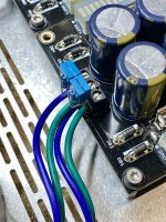
I added my snubber components to the bottom of an existing amplifier power supply. I used the most convenient pads.
I added Cx to the pads of the transformer input connector. I added Cs/Rs from the rectifier pads and the other end to the filter capacitors return pads. My concern is the high currents seen at the filters caps. Anyone see any problems with this implementation?
Here are some pictures of what I did:
Attachments


There will always be some 'common' section of the circuit where both the high pulsed rectifier current is flowing, as well as the snubber transient current - those common sections are in the CT as well as the phase arm wires connecting the transformer over to the pcb, and the pcb traces to the first main filter caps.
Twisting the transformer CT and phase arm wires, on their way from the transformer to the pcb, and keeping those wires as short as practical, is likely all that can be done to manage the transients.
Twisting the transformer CT and phase arm wires, on their way from the transformer to the pcb, and keeping those wires as short as practical, is likely all that can be done to manage the transients.
Of course, from the value of the resistor needed to quench the ringing, you can derive the value of the leakage inductance...
It's even quicker if you don't bother to install the trimpot or to carefully dial up the ideal critical damping.
Just measure the ringing frequency when Rs=infinity.
Ringing frequency f is a function of L and Cx and nothing else; you know f and you know Cx, solve for L.
But that's on the wrong side of the Venn Diagram, when you've decided to play around with "simple no-math transformer snubbers"
Just measure the ringing frequency when Rs=infinity.
Ringing frequency f is a function of L and Cx and nothing else; you know f and you know Cx, solve for L.
But that's on the wrong side of the Venn Diagram, when you've decided to play around with "simple no-math transformer snubbers"
A builder asks the question below. Since I feel the collective wisdom of all diyAudio readers far exceeds the wisdom of any one person, I am posting the inquiry to the membership at large. Anyone and everyone is invited to make a reply.
_
I'm messing with a cheapo modo and I was wondering if there is any advantage to fitting 2 snubbers to the centre tapped secondaries of a transformer. Ie one between each ac output and the centre tapping?
Many thanks
_
Last edited:
Ask him which came first, the chicken or the egg.
In all seriousness, he may be unsure about how to handle a centre tapped secondary, attach the snubbers across the entire winding, or split it in two and attach snubbers to each half.
In all seriousness, he may be unsure about how to handle a centre tapped secondary, attach the snubbers across the entire winding, or split it in two and attach snubbers to each half.
Per Mark's Quasimodo paper on page 11. I followed the layout there (last one) for CT snubbers on my dual PSU Salas DCG3 pre. Worked out perfectly.

Attachments

Last edited:
Ditto for me, is pretty well covered in the documentation where mentioned above.
I recall somewhere Mark also addressed the merits of using duplicate values from the first measured leg on the second leg, vs re measuring it. I believe he felt duplicating the values was satisfactory.
Bill
I recall somewhere Mark also addressed the merits of using duplicate values from the first measured leg on the second leg, vs re measuring it. I believe he felt duplicating the values was satisfactory.
Bill
Guys, this question came from me.
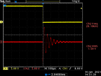
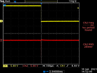
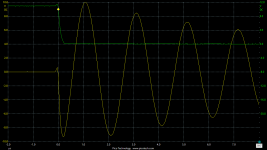
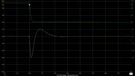
I've been trying out some snubbers on my Bedini 802 with the aid of the Cheapomodo. I've found that I can get the same result (a happily snubbed response curve) with either a pair of snubbers across the centre tap or a single snubber across the secondaries. Obviously in each case the resistor value is different. It might be that there is something peculiar to this amp, but in this instance I can't measure (or hear) any advantage to using 2x the component count.
I've been trying out some snubbers on my Bedini 802 with the aid of the Cheapomodo. I've found that I can get the same result (a happily snubbed response curve) with either a pair of snubbers across the centre tap or a single snubber across the secondaries. Obviously in each case the resistor value is different. It might be that there is something peculiar to this amp, but in this instance I can't measure (or hear) any advantage to using 2x the component count.
You may be spot on, but it would help if you showed all the steps you took, the results of each and maybe some theory to support your claim, posed as a question. Mark provides his data with his example circuits. My response comes from the perspective of one who doesn't have the training or experience to essentially know the answer. So I value data and theory that supports and demonstrates validity. I have used Marks suggested circuit with excellent results, but wouldn't have without his excellent supporting data as well. In the discussions he may have touched on why one is preferable.
I strongly recommend two C+RC snubbing networks for a center tapped transformer, as shown in the Quasimodo design note. However, whenever someone asks "would it be okay if I did XYZ my own way, differently than in the documentation?" I generally reply: "If you know what you're doing, enjoy yourself and do whatever you like, you don't need my advice. If you DON'T know what you're doing, follow the Quasimodo design note."
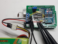
Another parts-bin build, this time on an Arduino proto board using the Arduino as the oscillator (ArduModo?), with 2 outputs in parallel to directly drive a twin D4184 MOSFET module I had to hand - total overkill on specification, but hey it does the job. IC socket for the two C's. Powered from 3S Lipo giving ~11v. Tested here with 10uH inductor, and like many others, works a treat! Thanks!
Attachments
Last edited:
- Home
- Amplifiers
- Power Supplies
- CheapoModo: quick and dirty transformer snubber bellringer jig