Finally you should post your measurements to the vendor thread, not the DIY thread..
Beside this,
the reports are kinda useless for most of us and, there's something really wrong with your setup from the gain aspect.
The f-sweep from 20Hz-20kHz shows a bandwitdh of 500Hz to 12kHz.
All your measurements where taken at lowest possible gain with 100mVrms..
That's a whooping 1Vrms into 4R -> 0.25W.
If you want to show the uber performance of your amp, do plots like shown in the datasheet so it is comparable. Everything else is just "reactive power".
I'm sorry for not being the nice guy regarding this issues.
Last edited:
Finally you should post your measurements to the vendor thread, not the DIY thread..
Beside this,
the reports are kinda useless for most of us and, there's something really wrong with your setup from the gain aspect.
The f-sweep from 20Hz-20kHz shows a bandwitdh of 500Hz to 12kHz.
All your measurements where taken at lowest possible gain with 100mVrms..
That's a whooping 1Vrms into 4R -> 0.25W.
If you want to show the uber performance of your amp, do plots like shown in the datasheet so it is comparable. Everything else is just "reactive power".
I'm sorry for not being the nice guy regarding this issues.
I have been asked multiple times to post the measurements on this forum and did so. I am very careful not to advertise or lately even mention the name of our product because I try my best to comply with the rules of this forum.
All your measurements where taken at lowest possible gain with 100mVrms.. That's a whooping 1Vrms into 4R -> 0.25W. .[/QUOTE said:Sorry , but I think you are wrong. Gain is clearly marked as 20.7db (thats its setting for the amp) so check again your calculation 1Vrms into 4R -> 0.25W. and tell me...is it correct ?
And?
100mVrms x 20dB = 1Vrms
20dB = x10
1Vrms²/4R = 0.25Wrms
Alright then. 🙂
For your inspiration to show proper results:
http://www.3e-audio.com/wp-content/...o Performance Measurements_EAUMT-0140-2-A.pdf
100mVrms x 20dB = 1Vrms
20dB = x10
1Vrms²/4R = 0.25Wrms
I have been asked multiple times to post the measurements on this forum and did so. I am very careful not to advertise or lately even mention the name of our product because I try my best to comply with the rules of this forum.
Alright then. 🙂
For your inspiration to show proper results:
http://www.3e-audio.com/wp-content/...o Performance Measurements_EAUMT-0140-2-A.pdf
Last edited:
There are the 2.1V input data, but the 19V PSU makes those useless? The 10kHz/15kHz/20kHz data using Aes17 brickwall 20kHz filter show ...what ?
Frequency curve probably the A wt setting, so data weighting to that curve ?
Frequency curve probably the A wt setting, so data weighting to that curve ?
hmmm , yeah I stand corrected.
Will take the same readings with 1w , 10w , 20w . Will open a new thread in vendor forum.
Will take the same readings with 1w , 10w , 20w . Will open a new thread in vendor forum.
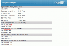
The 2.1Vrms setup is for connection check only.
From the rms-values of this test it can already be seen that there's something wrong with the gain of the tested amplifier.
At 15k with 2.1Vrms input:

With only 100mVrms input gain increases by 3dB..

Power compression? Or weak power supply..
Anyway, no 20dB here.
From the rms-values of this test it can already be seen that there's something wrong with the gain of the tested amplifier.
At 15k with 2.1Vrms input:
With only 100mVrms input gain increases by 3dB..
Power compression? Or weak power supply..
Anyway, no 20dB here.
Attachments

There are the 2.1V input data, but the 19V PSU makes those useless? The 10kHz/15kHz/20kHz data using Aes17 brickwall 20kHz filter show ...what ?
Frequency curve probably the A wt setting, so data weighting to that curve ?
Yeap the 19v make them useless... anyway our testing team is redoing everything. Any comments see you guys on new thread.
There are the 2.1V input data, but the 19V PSU makes those useless? The 10kHz/15kHz/20kHz data using Aes17 brickwall 20kHz filter show ...what ?
The AES17 LP is specified at:
[FONT=Verdana, Arial, Helvetica, sans-serif]±0.10 dB,10 Hz–20.0 kHz
Source: AES17 Filter
[/FONT]
With 20kHz setting, so this shouldn't affect the responce at all.
Yeap the 19v make them useless... anyway our testing team is redoing everything. Any comments see you guys on new thread.
Where is the new thread?
AES17 doesn't affect respons below 20kHz, I meant it can't show any meaningfull THD.
If frequency respons of that ampboard is like the graphs show, I would have expected people posting experiences with the ampboard to write about the total lack of bass and mid.
If frequency respons of that ampboard is like the graphs show, I would have expected people posting experiences with the ampboard to write about the total lack of bass and mid.

...Will open a new thread in vendor forum.
Post a link here when you have and I'll move all the relevant stuff over. Until then, can we all hold off this discussion as it makes finding and moving all appropriate posts much harder work. 😉
Unless of course, some generous person wants to draw up the list of post numbers for me! 😀
last post...team is working on new testing as soon as its done we will create thread and post results.
hmm , this is the last post.
First testing (1W) posted more coming, I wont link to it, look for it in the vendors bazaar.
First testing (1W) posted more coming, I wont link to it, look for it in the vendors bazaar.
question for doctormord
I am playing around with the tpa3128 ampboard with the se->diff inputstage like 32xx evm's and the more extensive outputzobel (part of postfilter feedback for evm's).
Inputcapacitors are 10uF. Is it to be expected that the simple 3 component antipop as proposed (360customs.de) for standard tpa31xx boards produces a cracking sound when powering on and off with these different value inputcapacitors or different input circuit ?
- Home
- Amplifiers
- Class D
- Cheap TPA3118D2 boards, modding them and everything that comes with it