Can anyone comment on this?Is the quality of the C connected to pin 5 important if the board is SE pbtl?
I wonder if this would be an easy mod to the sanwu 3118 without too much smd-fiddling:
-remove C41 and put a bridge in its place
-connect a quality film cap to the 'input-hole'
-leave C21 as it is
In the datasheet i only read that the caps should be the same value but not the same type.
"For good transient performance, the impedance seen at each of the two differential inputs should be the same."
Source has output impedance and capacitance, interconnect isn't ideal, so even when capacitors used on positive and negative input are identical, both inputs will see different impedance. Different capacitors could put them further apart, capacitor to ground always being lower impedance I guess.
Phase shifts are the result of unequal impedance at inputs, I remember seeing in simulations. That would add to 3rd harmonic distortion I guess.
"For good transient performance, the impedance seen at each of the two differential inputs should be the same."
Source has output impedance and capacitance, interconnect isn't ideal, so even when capacitors used on positive and negative input are identical, both inputs will see different impedance. Different capacitors could put them further apart, capacitor to ground always being lower impedance I guess.
Phase shifts are the result of unequal impedance at inputs, I remember seeing in simulations. That would add to 3rd harmonic distortion I guess.
Is this worse than the piezoelectric effect generated by the smd ceramic cap?
Are those x7r on the sanwu board?
Doctormord measured higher THD for a through hole filmcapacitor, because that one picked up/ received outputswitchingfrequency. So being an antenna in that example is worse than some vibrating for measured distortion.
I don't expect x7r, I expect every 10th of $cent to count 🙂
I don't expect x7r, I expect every 10th of $cent to count 🙂
I'm too lazy to read everything in the thread, just thought I would post what I measured on these amps recently. For some reason I saw a small drop in distortion when I jumpered D3 too, but did not save the measurement.
Picture of a board:

Unmodified board 19V laptop supply 4 & 8 ohm resistive load:


Input and output capacitors replaced, gain resistor removed (R27 was it?)


Picture of a board:

Unmodified board 19V laptop supply 4 & 8 ohm resistive load:


Input and output capacitors replaced, gain resistor removed (R27 was it?)


Another note: Due to my setup, I can only measure one side of the bridged output relative to ground. I can see a couple of dB diffrence in the distortion between the + and - outputs, I guess this is due to tolerances in components or the layout of the PCB.
May you do a THD vs. Pout for both sides please?
Which soundcard is used for the measurements and what are your timing settings?
Which soundcard is used for the measurements and what are your timing settings?
I can try to do that when I have time.
The soundcard is a Behringer UCA 222. Not sure what you mean by timing?
These measurements were 'best case' I cranked the amplitude until distortion started to rise, and then backed off to the 'sweet spot'. I think p-p amplitude (for one side) was a little bit over 10V.
Earlier I have done some measurements on other (analog) amps for reference, and the results are what I expected (really good good compared to class d).
Also did the SURE TDA 7492 boards Trevor Marshall modded (Trevor Marshall - Class D Audio Amplifier Design - TDA7498 Output filters) and got results in the same ballpark as him.
Measurements seem to 'bottom out' around -100dB with my hardware which I would think is enough for me to play around with.
Anyway, I like the sound of electric guitar, and how many % distortion does that have 😉 I don't take it too seriously, I just find it a bit interesting to measure and see how that compares to what my bad hearing tells me..
I'm just using the standard settings in steps, not sure how many frequecies are measured, but I guess it averages it between the measured points. No idea if it can do burst measurements, just doing sine waves at a specified number of frequency steps.
I measured the amp with a std 12V atx PS first, and the dist-curves where definitely not as smooth, especially in the lower frequencies. Much nicer with the dell 19V laptop supply.
BTW I have not calibrated the setup with voltage levels for proper power figures etc, too much work to adapt to diffrent amp gains etc, and I'm a beginner with ARTA too.
When I tried to use it for speaker measurements I gave up, too complicated, I wanted to start measuring quick, and Holm Impulse did the trick for that. Impatient and lazy are the keywords here 🙂
averaging or smoothing ?
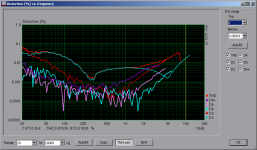
here are some measurements of another chinese noname TPA3118D2 stereo board.
noname TPA3118 stereo vs EMU0204
The board sounds great on 6 ohm speakers.
Measured with RMAA and REW on dummy resistor load 4 / 8ohm.
BTL output measured on balanced soundcard input through a FilterBox inspired by TI's app report http://www.ti.com/lit/an/sloa107/sloa107.pdf
I wish someone could measure the "higher end" Volt+ board like this.
any progress ? 🙂Dhl is bringing some pcb's and Fedex is bringing some Texas chips. After reception I check parts I have in stock and then order some I don't have and then I get headache from soldering 🙂 After that I may have an idea about pffb and tpa31xx.
averaging or smoothing ?
here are some measurements of another chinese noname TPA3118D2 stereo board.
noname TPA3118 stereo vs EMU0204
The board sounds great on 6 ohm speakers.
Measured with RMAA and REW on dummy resistor load 4 / 8ohm.
BTL output measured on balanced soundcard input through a FilterBox inspired by TI's app report http://www.ti.com/lit/an/sloa107/sloa107.pdf
I wish someone could measure the "higher end" Volt+ board like this.
I will ask our team to study and try.
About piezzo electric effect...
I play with my chinese TPA3118D2 stereo BTL board.
While doing a measurement on a resistive load, all should be dead silent.
What I surprise when I heard the sine sweep coming from the board itself! The level depends on the mesurement level. Of course, it's not loud. Need to listen close to the board to hear it.
Interesting is that the sweep becomes audible above 1kHz, precisely when THD starts to raise.
piezzo effect of ceramic capacitors ? which caps are suspects ?
inductors ?
has anyone experienced that before ?
In theory this could mechanical couple back into MLCC ceramics and force some piezoelectric effects but is uber most unlikely.
Finally we got the right cable for our AP machine (bnc to rca, good quality) and we tested the THD+N and SNR of our amp at different frequencies .
Attachments
- Home
- Amplifiers
- Class D
- Cheap TPA3118D2 boards, modding them and everything that comes with it