To state it simple: it makes absolutely no sense to test a 30A inductor when late ron a different 8A type is chosen. maybe I am too scientific thinking but that is how I deal with challenges. Yes, only conclusion is again that it is better and enough material to debate on. No real data though what final situation will be.
Seems like you don't understand the point:
It pretty much makes sense to check the systems limits first rather than testing several different inductors not knowing if the next (untested) one might be better. This is a never ending story. The results from this measurement/test shows the limits of the inductors influence on compression/saturation.
If you have a different approach, then go for it. I'll do it my way. 😉
@ irribeo: Let's not introduce yet another set of variables. Maybe, just maybe it would occur that testing with same conditions is the only way to get consistent test results otherwise I think this thread will reach 5000 posts easily.
@ doctormord: I fully understand your point. You choose an unrealistic large overrated part to see if it improves results. It does. We can conclude that the stock inductors are too light as they saturate while a XXL 30A type does not. Normally then a fitting part is chosen that will be mechanically and electrically optimal for the task. call it a trade off. Then that one is measured and if it measures way better than the stock inductor the goal is reached. If I need to explain that most probably won't want a very large and heavy part connected with wires I think I will put my time in something else.
@ doctormord: I fully understand your point. You choose an unrealistic large overrated part to see if it improves results. It does. We can conclude that the stock inductors are too light as they saturate while a XXL 30A type does not. Normally then a fitting part is chosen that will be mechanically and electrically optimal for the task. call it a trade off. Then that one is measured and if it measures way better than the stock inductor the goal is reached. If I need to explain that most probably won't want a very large and heavy part connected with wires I think I will put my time in something else.
Last edited:
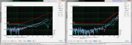
Close. It also shows the limits of improvement by only changing the inductors. Smaller inductors won't usually get any better than this.I fully understand your point. You choose an unrealistic large overrated part to see if it improves results. It does.
Secondly, when comparing this and the other measurements (which i haven't posted yet, as they're many) i'd taken, there will be similarities for both types of inductor. This then shows, what can't be improved by just changing the inductors.
Example:
1W into 4R at 12V
Stock inductors LEFT, SER2915H RIGHT
The improvements are in the range of 200-2k.
Attachments
Last edited:
Sanwu filter is 4 ohm, ceramic capacitor class II capacitance change with AC will have Sanwu peaking at low levels, adding harmonic dB's. EVM filter is 6 ohms, with 4 ohm normally overdamped, ceramic class II might get it less overdamped at low levels. And pbtl should generally show minor higher thd compared to btl too, but if not 4 ohm filter change was made on EVM, I don't know they did or not, pbtl data TI could also be with some harmonic attenuation. Doctormord showed up to 5th harmonic 6kHz I believe, that also is beyond TI used AES filter.
The coilcrafts should distort less at higher levels than toko's or toyo's TI uses, but those are probably selected for being flat till 7 or 8A, so difference might not be too big, I didn't look at those in TI comparison. I do know from personal experience the Coilcraft and Wurths sound different, more treble with Wurths, but could just be small value difference, I never checked that then.
Then other parts of TI test setup probably different, powersupply probably also different, etc etc. Doctormord probably used setup more like the tpa32xx special setup used by TI to show higher bandwith ?
^^^ LOL. Jean-paul tries for 12 hours to herd cats, realizes you can't herd cats, calls it a night.
Last edited:
Well put ! It indeed feels like that. It seems that no method is avoided to introduce as many hurdles as possible to frustrate consistent results. A slippery and dangerous road to a destination we are apparently not allowed to reach .... a tested and proven set of modifications that can lead to consistent and reproducible results for every Sanwu TPA3118 board owner (preferably with a small BOM with known costs).
* Despite all technicalities, apparently unsolvable imperfections, sudden counterattacks by yet another abbreviation and all the horror we see in diagrams (even fake chips) let's not forget that these boards already sound good without any mod. Better than most other boards too. This thread needs better inductors to filter THD and noise IMO.
* Despite all technicalities, apparently unsolvable imperfections, sudden counterattacks by yet another abbreviation and all the horror we see in diagrams (even fake chips) let's not forget that these boards already sound good without any mod. Better than most other boards too. This thread needs better inductors to filter THD and noise IMO.
Last edited:
??? Then do better than just whining about..It seems that no method is avoided to introduce as many hurdles as possible to frustrate consistent results.

It is me that tries to bring clarity in the mist you both create. Indeed the thought came up to get my stuff out of storage. I know an A4 (Letter for US people) with recommended mods and some pictures will do for most.
Last edited:
Don't tell me you want to reach the finish 🙂 Even when you're 1 meter before it irribeo will come up with a new issue. ---> "Doctor, Sanwu has the I guess cutable bottom track from input to powerground entry, which affects audible noise at least, don't know how it measures of course." If not I will come up with one 🙄
Just joking, have it all your way. I am off to bed.
Just joking, have it all your way. I am off to bed.
Last edited:
If you check measurements of groupbuy boards here, browse, you'll see TI EVM datasheet values can not be reached, with what was thought best possible layout and components, for Dugs including the 30A+ overkill inductors others include superior regarded and often tested Icecomponent inductors. Protection tripping or actually not tripping might be a sign of surprising layout Sanwu working for this chip, measurements might also show limits of this layout or implementation, thermal limits could be one obvious difference that might affect higher voltage too.
Doctormord kindly takes time and shows measurements, showing much more than I can immediately see or understand. Impatiently I would like to be presented with final solution now too, maybe buying a 360design tpa3132 is fastest way and maybe also cheaper, more sensible 😀 No filter to affect anything LOL all your speakers will work, EMI is documented by measurements too 🙂
Doctormord kindly takes time and shows measurements, showing much more than I can immediately see or understand. Impatiently I would like to be presented with final solution now too, maybe buying a 360design tpa3132 is fastest way and maybe also cheaper, more sensible 😀 No filter to affect anything LOL all your speakers will work, EMI is documented by measurements too 🙂
Well next hurdle: maybe Sanwu uses Y5 ceramics, dropping 99% of value at 24V and 28V, creating trouble with higher voltages compared to EVM 🙂
My phone bleeped again. Maybe it is the blue solder mask containing boron nitride having a spurious induction on the Di/Dt of the PSU capacity forcing a differential voltage over the ground plane of the left input. It could be that AM2 setting to high could solve it. Or replacing the ferro connectors for plated copper ones. With less Gauss it could be that radiation goes counter clockwise thus enhancing the already good Sanwu layout of the PCB. Could be as I am already busy testing a TPA3666 on the board. I will need to cut some tracks and try composite inductors despite TI recommending not to use them as they have 13.5% more THD than the stock ones.
Last edited:
OK , we see proof for the assumption/empirical results that the stock inductors are too light as they saturate way below the power the chip can deliver. The one that is replacing it however is not a suitable replacement with regards to its size. I think it is better to avoid flying lead wires so a higher rated inductor that fits on the original pads of the board would be optimal.
Did you see the one that I linked to ? Or the Würth WE-PD irribeo linked to ? The Würth seems to saturate at thrice the current of the original inductors.
Possible the reason 2nd-3rd generation generic copies sound great is what we are calling dynamic filter saturation?
THD as an absolute metric is having trouble correlationing with 'sounds good'.
The SET people have known this for years.
d-class topology i always suspected could 'sound good' like SET , the ti tpa311x is first for me to hear meeting that 'good sound'.
There may be others, but i have not auditioned.
I only use 24v 7.5 type smps for the sanwu/yj tests. no experience with other voltages.
A big topic these days on THD as a metric in thread "whats wrong with op-amps"
http://www.diyaudio.com/forums/everything-else/169484-what-wrong-op-amps.html
.
Not likely as those that replace inductors for heavier rated ones report a better sounding amplifier. Measurements in the previous pages also show better numbers with higher rated coils that don't saturate at "normal" sound levels.
IMHO these amplifiers benefit from a very low output impedance giving good control over the loudspeakers.
IMHO these amplifiers benefit from a very low output impedance giving good control over the loudspeakers.
The 3118 pbtl has higher dampingfactor, 3128 pbtl even little higher. Higher than STM chip amps or other "single" die amps. In lower gainsetting probably higher than standard high gain setting, low gainsetting (increased internal feedback) could also affect treble distortion.
When voltage derates the classII ceramics supplying and filtering power, I could see higher output trouble at higher voltages. The current single buy huge profit including sellingprice is $1.59(cheapest clone, of several different clones) to $2.59 (Sanwu), making it logical they used what ever part was available cheapest.
When voltage derates the classII ceramics supplying and filtering power, I could see higher output trouble at higher voltages. The current single buy huge profit including sellingprice is $1.59(cheapest clone, of several different clones) to $2.59 (Sanwu), making it logical they used what ever part was available cheapest.
Knowing that it is profitable in China to reuse old parts from scrap boards I replace ceramic caps on ultra cheap electronics for known good ones. What else can we expect for the prices the boards are offered for ? In theory one should know better and indeed make an improved PCB, buy original parts and design the boards with possibility for film caps at the inputs and larger coils.
Or try to improve the existing boards with known good parts as suggested and mod it to the max. For that one needs consistent test methods (beware this would indicate systematical approach!). Not going back and forth adding every possible variable. I am quite sure that replacing coils for suitable ones and some other slight mods are enough. All the garble about GND planes and possible influences while knowing theses boards are amongst the best sounding won't bring much as the board is a given parameter. Better focus on what can be done in real life.
I think the latter is what most do here (or want to do) otherwise they would not have bought the boards. So the PCB and chip are no variables. The PSU voltage, caps, resistors and inductors and all their respective values/ratings are. So a wise man would focus on these and keep track of what he is doing.
Last edited:
- Home
- Amplifiers
- Class D
- Cheap TPA3118D2 boards, modding them and everything that comes with it