Define "normal", maybe it is better to also mention impedance.
If the Sanwu functions with twice the output voltage before tripping we know it will not dislike difficult loads and/or it can play loud. You did not say it sounded horrible or distorted .... For knowing what we are doing we would listen/measure and evaluate and compare to the boards in our possession that have the same chips. We would leave out garble about possible fake chips and leave those out of the equation. Then we would make the choice to mod or not. After experimenting and modding we would measure/listen again and choose the best one of all TPA amplifiers in our posession. If the humble 6.99 $ Sanwu turns out to be the best sounding/measuring a final recommendation can be made to anyone willing to work on the very same boards with consistent results.
At least that is the way that is most efficient to a broad public.
Last edited:
Due to space limitation and current needs, i'd suggest to use inductors as low as 5-6u8H with 680n-1u. (With 65kHz filter frequency)
This one ? Please check. I don't have my boards at hand but I hope these will fit as specifications are OK. I recall the ones on the board to be 10 x 10 mm.
74439358047 - WURTH ELEKTRONIK - Surface Mount Power Inductor, WE-XHMI Series, 4.7 µH, 9.5 A, 20.5 A, Shielded, 0.00865 ohm | Farnell element14
74439358047 - WURTH ELEKTRONIK - Surface Mount Power Inductor, WE-XHMI Series, 4.7 µH, 9.5 A, 20.5 A, Shielded, 0.00865 ohm | Farnell element14
Last edited:
The 16u HCI with standard Sanwu ceramic capacitor is just like the 6 ohm TI 10u/680n, just not 60kHz but 40kHz. Replacing the inductors imo is most times needed, replacing all outputfilter components to get 60kHz filter might be better, you justhave more of the switchingfrequency, probably the zigzag seen on earlier sinewave picture. To reduce that set AM1 pin high, and because you now might need to leave any Sanwu or clone for not being TI out of comparison, making own board might seem good option.
That might have Sanwu layout similarities to function when others stop functioning.
That might have Sanwu layout similarities to function when others stop functioning.
Sorry my friend but designing a new board is again a different subject. Out of reach for most too. We can't shoot a moving target can we ?
We are dealing with a ready made 6.99 $ Sanwu TPA3118 board that needs to be optimised in its current form and those that have soldered many of these to death and have worn out their scope tubes on them can give input what to do. Or what not to do. I can tell you to bake a cake but i am sure you would ask me "what cake ?". Chocolate cake, vanilla cake, cheesecake ? How much eggs, how much flour ? How much butter ? What butter ? I would answer you that I want a good cake that I will most probably like and you would still know nothing 😀
* elaborate on "setting AM1 high" preferably with a picture and measurement. What does it do, how do we do it and what will it improve ?
Last edited:
maybe can buy the bare generic boards?
or take a look at xray? dont think gerbers are forthcoming.
.
or take a look at xray? dont think gerbers are forthcoming.
.
Switching frequency is set by AM pins. Outputfilter is there to attenuate switchingfrequency. I you set switchingfrequency higher and use same outputfilter, the switchingfrequency gets attenuated more. Doctormord posted pics of sinewave recently, showing how filtering and lowering avcc affected output. The highfrequency waveform riding on the sinewave probably is switchingfrequency, increase this frequency and amplitude on top of sinewave gets lowered too.
If you want a good tpa3118 ampboard, first you need a tpa3118, if you want to mod tpa3118 first you need tpa3118, if you want to discuss 3118, first you need tpa3118.
You mentioned leaving out counterfeit chip boards, so how do you include modding an ampboard that might only be available with fake chip. That is your target, I didn't move
Since it has no solid groundplane a lamp will do 🙂 That is why I said my last board was almost a copy, tracks shape and route almost entirely like Sanwu, size identical to Sanwu too.maybe can buy the bare generic boards?
or take a look at xray? dont think gerbers are forthcoming.
.
I changed the inductors for Coilcraft SER2915H-103 (10uH), knowing, these inductors wont saturate at all. Measurements where taken into 4R load.
Comparison at 1kHz:
Stock inductors:
SER2915-103H:

Comparison at 6kHz:
Stock inductors:

SER2915-103H:

To me it looks like the stock inductors start to saturate at ~4.5Vrms or 5Wrms or 1.6A. (Seems legit)
Comparison at 1kHz:
Stock inductors:
SER2915-103H:
Comparison at 6kHz:
Stock inductors:
SER2915-103H:
To me it looks like the stock inductors start to saturate at ~4.5Vrms or 5Wrms or 1.6A. (Seems legit)
Attachments
Last edited:
LOL those together are same size as entire ampboard 🙂 Lower thd 12V than EVM, but not too much surprise there with these, still looking and comparing other voltages 🙂
Small PD I used for Sure and a Sanwu, equal shape almost entirely equal looking so no visual benefit from desoldering and soldering effort at all 🙂
http://katalog.we-online.de/pbs/datasheet/7447714100.pdf
Small PD I used for Sure and a Sanwu, equal shape almost entirely equal looking so no visual benefit from desoldering and soldering effort at all 🙂
http://katalog.we-online.de/pbs/datasheet/7447714100.pdf
Totally oversized, of course. Just to cancel out the effect of the inductors and to see whats similar with both inductors (stock & Coilcraft). What's left then is "generated" by something else.
OK , we see proof for the assumption/empirical results that the stock inductors are too light as they saturate way below the power the chip can deliver. The one that is replacing it however is not a suitable replacement with regards to its size. I think it is better to avoid flying lead wires so a higher rated inductor that fits on the original pads of the board would be optimal.
Did you see the one that I linked to ? Or the Würth WE-PD irribeo linked to ? The Würth seems to saturate at thrice the current of the original inductors.
Did you see the one that I linked to ? Or the Würth WE-PD irribeo linked to ? The Würth seems to saturate at thrice the current of the original inductors.
Last edited:
The SER2915H are actually connected with 2mm² copper wires to the board, length ~2cm. Radiation is a bit higher when mounted like this, but okay for the test.
Once i finished the other tests, i'll try a MSS1278-103. (Which still is to big to be mounted directly.)
Once i finished the other tests, i'll try a MSS1278-103. (Which still is to big to be mounted directly.)
For optimal results and lowest possible radiation an inductor directly soldered to the board (as it should be) seems best choice. That extra radiation won't improve measurements nor real life situation.
Secondly it makes little sense testing mega large coils when a different type is chosen in the end and the latter stays untested. We will still don't know consistent results. Improving is choosing a suitable part, then measuring it to verify if it really is an improvement.
Secondly it makes little sense testing mega large coils when a different type is chosen in the end and the latter stays untested. We will still don't know consistent results. Improving is choosing a suitable part, then measuring it to verify if it really is an improvement.
Last edited:
Well, the SER2915H don't fit to the board. 🙄
How should i measure them, if not connected by wire? 😕 😉
Beside this, through-hole toroid inductors aren't directly mounted to the board as well.
The inductor linked by you:
74439358047 - WURTH ELEKTRONIK - Surface Mount Power Inductor, WE-XHMI Series, 4.7 µH, 9.5 A, 20.5 A, Shielded, 0.00865 ohm | Farnell element14
is much like the XAL series from Coilcraft, made from a composite.
From the TI inductor shootout, they are a magnitude worse than the MSS1278 at 78W. (0.23% vs. 0.024%)
Secondly it makes little sense testing mega large coils when a different type is chosen in the end and the latter stays untested. We will still don't know consistent results. Improving is choosing a suitable part, then measuring it to verify if it really is an improvement.
Come on mate, please be so kind and read my posts. 😕
Totally oversized, of course. Just to cancel out the effect of the inductors and to see whats similar with both inductors (stock & Coilcraft). What's left then is "generated" by something else.

It pretty much makes sense to check the systems limits first rather than testing several different inductors not knowing if the next (untested) one might be better. This is a never ending story. The results from this measurement/test shows the limits of the inductors influence on compression/saturation.
Last edited:
The Würth WE-PD then ? Many will not want to use flying inductors. I know I would not want that for sure. Boards should stay as compact as possible.
I do read your posts and I do answer (contrary to some). However:
To state it simple: it makes absolutely no sense to test a 30A inductor when later on a different 8A type is chosen. Maybe I am too scientific thinking but that is how I deal with challenges. Yes, only conclusion is again that it is better and enough material to debate on. No real data though what final situation will be.
I do read your posts and I do answer (contrary to some). However:
For optimal results and lowest possible radiation an inductor directly soldered to the board (as it should be) seems best choice. That extra radiation won't improve measurements nor real life situation.
Secondly it makes little sense testing mega large coils when a different type is chosen in the end and the latter stays untested. We will still don't know consistent results. Improving is choosing a physically suitable part, then measuring it to verify if it really is an improvement.
To state it simple: it makes absolutely no sense to test a 30A inductor when later on a different 8A type is chosen. Maybe I am too scientific thinking but that is how I deal with challenges. Yes, only conclusion is again that it is better and enough material to debate on. No real data though what final situation will be.
Last edited:
Please read my previous post.
http://www.diyaudio.com/forums/clas...ng-them-everything-comes-168.html#post4962395
http://www.diyaudio.com/forums/clas...ng-them-everything-comes-168.html#post4962395
So you test tractor wheels on your Porsche too just to see if they improve road behaviour ? 😀
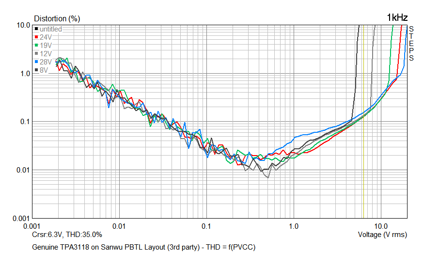
With 24 volt the Sanwu shows rise when EVM distortion is still dropping towards 10 watt/say 6 volt, there EVM distortion is lower. But Sanwu also is at 32dB gain, which ads distortion and adds noise and Sanwu has the I guess cutable bottom track from input to powerground entry, which affects audible noise at least, don't know how it measures offcourse.
- Home
- Amplifiers
- Class D
- Cheap TPA3118D2 boards, modding them and everything that comes with it