I'm planning to use PBTL3118 dual Mono boards for powering a pair of 6 Ohms speakers . If I want to use them for 16 Ohms speakers, then instead of changing output chokes can I use resistors (say 4.7R-10R)in parallel with 16 Ohms speakers to reduce overall impedance within its 4-8 Ohms impedance handling range. Little less power to speakers or power loss in parallel resistors it not an issue as its primary application is to use it for TV with a single 19V laptop brick adaptor. Common ground for inputs, seperate ground for outputs
I read somewhere that since the clocks are identical these will cause audible noise to creep in. Also TI application notes suggests "...The device can be configured for either master or slave operation by using the SYNC pin. This helps to prevent audible beats noise."
Or using 2X 19V bricks is a better option?
Adding resistors in parallel with the load will only put more stress on the amplifier chips - the voltage across the 16ohm speakers will remain the same (P = U^2 / R).
Separating the grounds as you say will only be achievable through cutting traces on the boards, i hope you're aware of that. Plus that none of the outputs are grounded anyway - perhaps you meant power grounds.
I'm powering a pair of those little boards out of the same 19V laptop brick (albeit the amp boards themselves are "on" the speakers, so physically separated), and all the noise i can hear out of them is some background hiss, with my ear right up against them. Although admittedly, i've slightly modded them in the sense that i cut a trace and made the input "balanced".
I'm planning to use PBTL3118 dual Mono boards for powering a pair of 6 Ohms speakers . If I want to use them for 16 Ohms speakers, then instead of changing output chokes can I use resistors (say 4.7R-10R)in parallel with 16 Ohms speakers to reduce overall impedance within its 4-8 Ohms impedance handling range. Little less power to speakers or power loss in parallel resistors it not an issue as its primary application is to use it for TV with a single 19V laptop brick adaptor. Common ground for inputs, seperate ground for outputs
I read somewhere that since the clocks are identical these will cause audible noise to creep in. Also TI application notes suggests "...The device can be configured for either master or slave operation by using the SYNC pin. This helps to prevent audible beats noise."
Or using 2X 19V bricks is a better option?
When using balanced inputs you’ll have the least problems. I recently had a project where i used 3 of the 3118 PBTL boards on one supply driven by a DSP in unbalanced configuration and there truely where a whining noise to clock frequency beating. The boards clock differs as much as 2%. After changing them to 1 master and 2 slaves the whiny where gone. All this happened even with carefully layed out ground connections and an isolated supply for the DSP. The more amps you have the more noise will be there.
I wired the sources so that maximum noise can be heard for debug reasons here:
YouTube
I wired the sources so that maximum noise can be heard for debug reasons here:
YouTube
Last edited:
Just for my personal interest: Did you have a diode at each amp´s power input, separating them from the supply, when you heard them "whining"?
So you recommend using the master/slave configuration with these amps? Or was it the first time you had such beat tones? Some here at the Forum consider this nonsense and advice to ignore the TI data sheet about m/s, even when using more than one 3116D2 (which should be hardly the same amp) with one power supply.
This would make using multiple amps, like in an active speaker much more complicated or even impossible, as most cheap amp moules don´t have the neccesary connections handy. I have not seen one with a connector or jumper to activat m/s. With most boards the relevant contact points are even hidden under the heat sink.
I always feared that would become a problem with DSP use.
As it fixed all my problems, i highly recommend using the master/slave configuration when using more than 1 amp. I haven't had any project with these 3118 PBTL boards before.
What i also noted, the noise is much more inherent when the amps are feed by a boost-converter than with direct battery. So there were 3 amp beating each other feed by a 100-150khz bost-converter.
Connecting them in m/s configuration is rather simple as the SYNC pin is on the edge of the TPA3118 and not connected to anything else. A simple wire is enough as the SYNC is clock/4 which results in 100khz - this can considered to be "DC". Filtering is not needed due to schmitt-trigger inputs.
To show the facts more clear:
Noise sources are:
3x TPA3118 Clock
1x ADAU1701 Clock
1x CSR64215 I2S Clock, BT RX/TX Burst
1x 150W DCDC Boost Clock
1x Buck Burst
1x Isolated DCDC load-variant clock modulation
All there "fight" against each other.
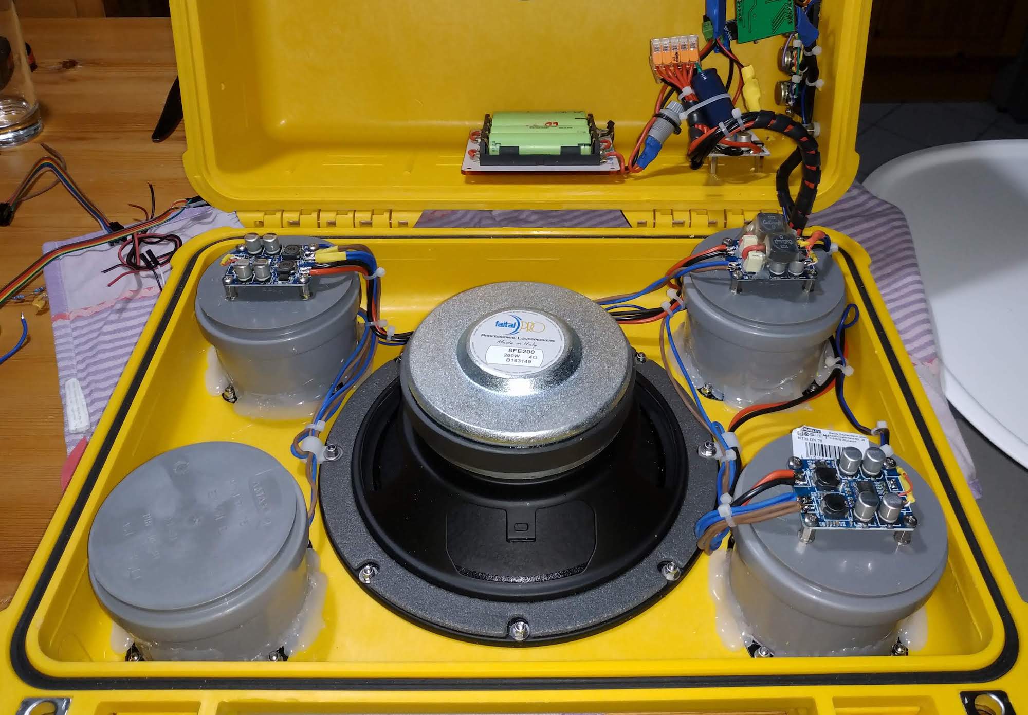
The speaker/amp configuration:
Separate clocks at the TPA3118 without sync:
1:
2:
3:

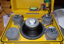
Power/Signal/GND-Connections are:
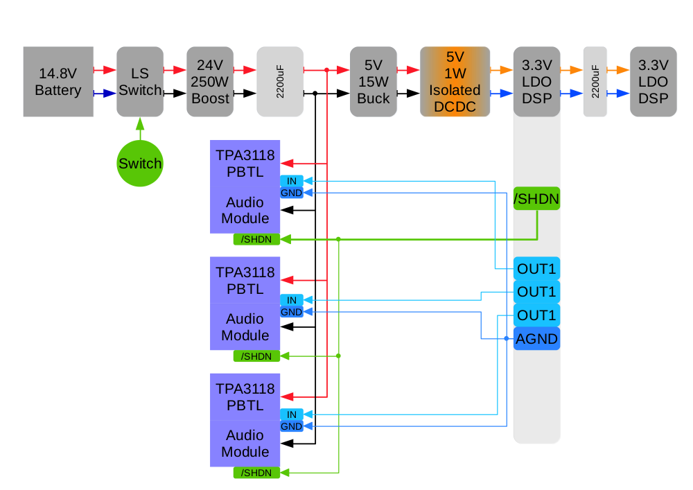
If you look closely, there are two low current loops via Signal-GND which may act as possible antennas:

Attaching GND at the high-current-gnd-point do not help here and may degrade the signal due to gnd-bounce and modulation, especially regarding "beat-noise". From practical testing it increases the background-noise-level.
So syncing all 3118 which just a single wire star-connected to the master fixed it. Gain-resistors needs to be adjusted, of course.
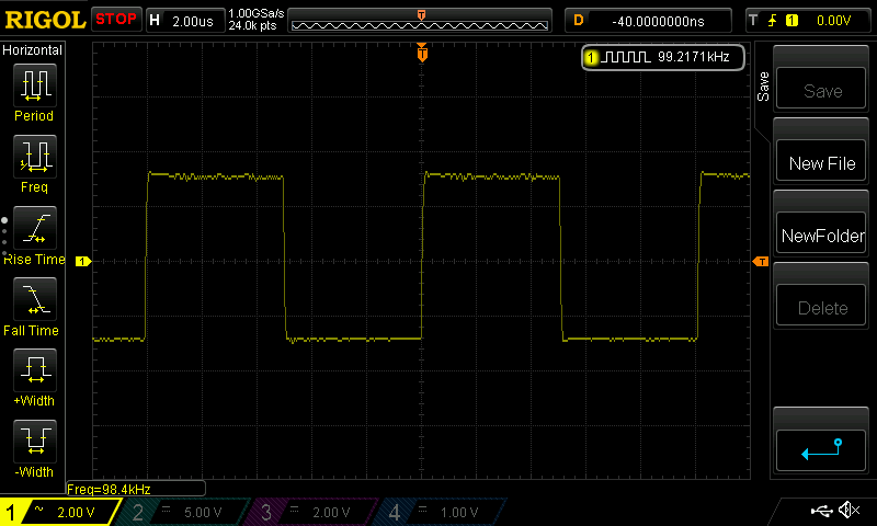
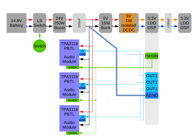
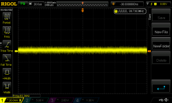
One thing is interesting to note, the CSR64215 is need from the ADAU1701 DSP 3.3V LDO. The voltage/noise level at this LDOs output is shown here:

This plot is valid if no BT-module is connected and looks pretty clean for the fact it is feed by:
16V battery -> 24V Boost -> 5V Buck -> 5V Isolated DCDC..
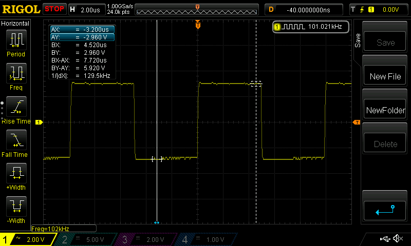
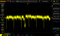
When the BT-Module is connected together with a 2200uF LowESR Hybrid-Polymer at an ESR of about 12mOhms, the following bursts are still seen at the LDOs input:

So there isn't any advantage from using additional MLCC here, as the bursts push even through the LDO to the input side. The 2200uF is hiding these bursts anyway and you wont here them. Without, they are barely hearable with the ears right next to the tweeters.
What i also noted, the noise is much more inherent when the amps are feed by a boost-converter than with direct battery. So there were 3 amp beating each other feed by a 100-150khz bost-converter.
Connecting them in m/s configuration is rather simple as the SYNC pin is on the edge of the TPA3118 and not connected to anything else. A simple wire is enough as the SYNC is clock/4 which results in 100khz - this can considered to be "DC". Filtering is not needed due to schmitt-trigger inputs.
To show the facts more clear:
Noise sources are:
3x TPA3118 Clock
1x ADAU1701 Clock
1x CSR64215 I2S Clock, BT RX/TX Burst
1x 150W DCDC Boost Clock
1x Buck Burst
1x Isolated DCDC load-variant clock modulation
All there "fight" against each other.
The speaker/amp configuration:
Separate clocks at the TPA3118 without sync:
1:
2:
3:
Power/Signal/GND-Connections are:
If you look closely, there are two low current loops via Signal-GND which may act as possible antennas:
Attaching GND at the high-current-gnd-point do not help here and may degrade the signal due to gnd-bounce and modulation, especially regarding "beat-noise". From practical testing it increases the background-noise-level.
So syncing all 3118 which just a single wire star-connected to the master fixed it. Gain-resistors needs to be adjusted, of course.
One thing is interesting to note, the CSR64215 is need from the ADAU1701 DSP 3.3V LDO. The voltage/noise level at this LDOs output is shown here:
This plot is valid if no BT-module is connected and looks pretty clean for the fact it is feed by:
16V battery -> 24V Boost -> 5V Buck -> 5V Isolated DCDC..
When the BT-Module is connected together with a 2200uF LowESR Hybrid-Polymer at an ESR of about 12mOhms, the following bursts are still seen at the LDOs input:
So there isn't any advantage from using additional MLCC here, as the bursts push even through the LDO to the input side. The 2200uF is hiding these bursts anyway and you wont here them. Without, they are barely hearable with the ears right next to the tweeters.
Attachments
-
 NewFile1.png40.9 KB · Views: 699
 -
 NewFile2.png34.2 KB · Views: 705
 -
 NewFile3.png34.7 KB · Views: 706
 -
 IMG_20190711_221156.jpg235.9 KB · Views: 720
 -
 PowerSignalDistributionDiagram.png69 KB · Views: 724
 -
 PowerSignalDistributionDiagram-2.png127 KB · Views: 698
 -
 PowerSignalDistributionDiagram (1).png129.7 KB · Views: 703
 -
 3v3out.png44.3 KB · Views: 700
 -
 dspin.png57.8 KB · Views: 712
Last edited:
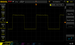
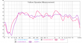
In the end, the speaker gets measured and equalized to this (dark purple):
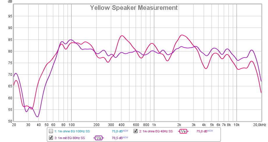
At this stage, the woofer where still tuned for lower fs by an additional mass of 10g.
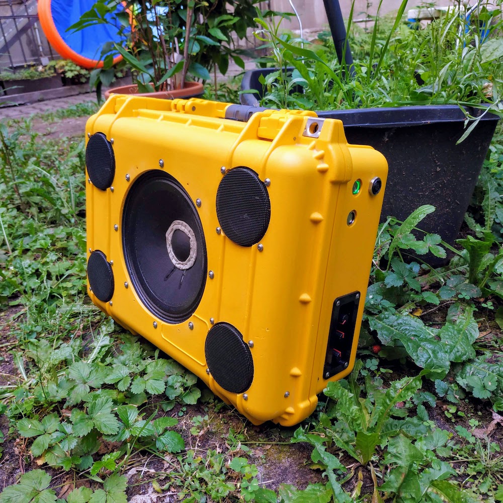
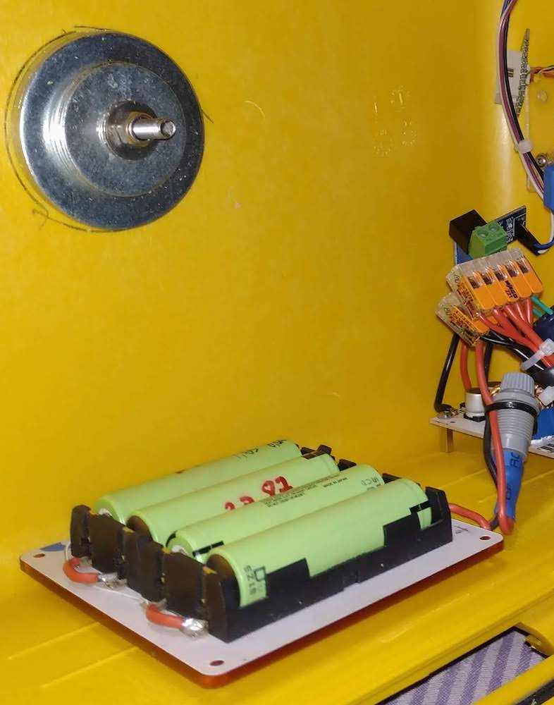
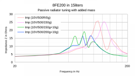
The enclosures backside is used as a passive radiator, which is tuned by a center-weight of exactly 200g. This way any BR holes/resonators are avoided. 🙂 Tuning frequency is slightly below woofers resonance frequency. (75-80Hz)
At this stage, the woofer where still tuned for lower fs by an additional mass of 10g.
The enclosures backside is used as a passive radiator, which is tuned by a center-weight of exactly 200g. This way any BR holes/resonators are avoided. 🙂 Tuning frequency is slightly below woofers resonance frequency. (75-80Hz)
Attachments


Thank you for sharing this nice project. A real "MARLEY" sound speaker system 🙂
Using the vibrating back side as as tuned radiator instead of silencing it is a clever idea. On first sight I would expect the sound to be questionable, but I trust your expertise, as stuff you do is always of high quality.
I have to take the microscope now, to find the sync pins of my 3116D2 boards
Thanks mate,
their where excessive (non automated) measurements done for the tuning:
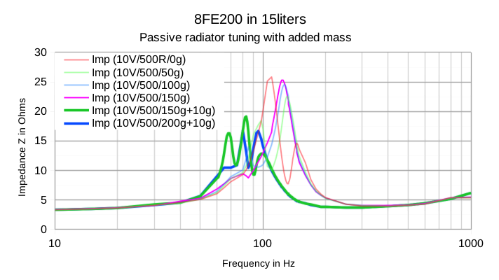
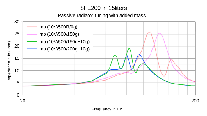
The measurements are done at 10Vrms output with a MAX9709. The Sub is then connected with 500R in series and the impedance is traced for different tuning masses at the backplate. The "+10g" indicated additional mass on the chassis-conus.
Undistorted peak-output (1khz) is actually 116dB(A) at 1m distance, or 96dB at 10m.
their where excessive (non automated) measurements done for the tuning:
The measurements are done at 10Vrms output with a MAX9709. The Sub is then connected with 500R in series and the impedance is traced for different tuning masses at the backplate. The "+10g" indicated additional mass on the chassis-conus.
Undistorted peak-output (1khz) is actually 116dB(A) at 1m distance, or 96dB at 10m.
Attachments

Last edited:
Hi all!
Is it appropriate and safe to mount a small heatsink to the rear of this board with thermal grease?
TPA3118D2 Digital Amplifier Board Amplificador Dual Channel Audio Amplifier Board 45W*2 For 4 8ohm Speaker Amp DIY-in Instrument Parts & Accessories from Tools on Aliexpress.com | Alibaba Group
Is it appropriate and safe to mount a small heatsink to the rear of this board with thermal grease?
TPA3118D2 Digital Amplifier Board Amplificador Dual Channel Audio Amplifier Board 45W*2 For 4 8ohm Speaker Amp DIY-in Instrument Parts & Accessories from Tools on Aliexpress.com | Alibaba Group
Hi all!
Is it appropriate and safe to mount a small heatsink to the rear of this board with thermal grease?
TPA3118D2 Digital Amplifier Board Amplificador Dual Channel Audio Amplifier Board 45W*2 For 4 8ohm Speaker Amp DIY-in Instrument Parts & Accessories from Tools on Aliexpress.com | Alibaba Group
You can mount a small heatsink on the rear side of the board with heat conductive glue as long as the heatsink ONLY touches the ground-plane. Else, you create a short-circuit.
You can mount a small heatsink on the rear side of the board with heat conductive glue as long as the heatsink ONLY touches the ground-plane. Else, you create a short-circuit.
Thank you. So on this board, as long as it touches no pins the PCB varnish enough to keep from shorting?
Thank you. So on this board, as long as it touches no pins the PCB varnish enough to keep from shorting?
No, it is not the varnish (solder mask) that prevents a fault. You have to keep the heatsink on the big copper-area only, which is the ground plane. Then the heatsink cannot touch any other copper track and there is no possibility for a short-circuit.
No, it is not the varnish (solder mask) that prevents a fault. You have to keep the heatsink on the big copper-area only, which is the ground plane. Then the heatsink cannot touch any other copper track and there is no possibility for a short-circuit.
OK, so thermal tape, although not the best conductor of heat, would be a better idea? Or mask the potential areas oh shorting with kapton tape?
Last edited:
OK, so thermal tape, although not the best conductor of heat, would be a better idea? Or mask the potential areas oh shorting with kapton tape?
What I propose is thermal glue which is quite like thermal grease but thermal glue hardens up. It is used to mount small heatsinks directly (without screws) on the amplifier chips for cheaper amplifier boards, such like TPA3116. The layer can be thin and my guess is the thermal properties are close to those of thermal grease.
What I propose is thermal glue which is quite like thermal grease but thermal glue hardens up. It is used to mount small heatsinks directly (without screws) on the amplifier chips for cheaper amplifier boards, such like TPA3116. The layer can be thin and my guess is the thermal properties are close to those of thermal grease.
Ah, I am beginning to understand.
So, this in combiation with masking potential areas of short with kapton tape?
Halnziye HY910 5g tube Silicone Heatsink Plaster / Thermal Adhesive Glue | eBay
A glue something like this: 3pcsx5g Thermal Pads Conductive Heatsink Plaster Viscous Adhesive Glue For Chip VGA RAM LED IC cooler radiator cooling-in Fans & Cooling from Computer & Office on Aliexpress.com | Alibaba Group
Yes, it is clever to protect areas with a risk of short-circuit using kapton-tape.
Yes, it is clever to protect areas with a risk of short-circuit using kapton-tape.
A glue something like this: 3pcsx5g Thermal Pads Conductive Heatsink Plaster Viscous Adhesive Glue For Chip VGA RAM LED IC cooler radiator cooling-in Fans & Cooling from Computer & Office on Aliexpress.com | Alibaba Group
Yes, it is clever to protect areas with a risk of short-circuit using kapton-tape.
Thank you! 🙂 🙂
...Separating the grounds as you say will only be achievable through cutting traces on the boards, i hope you're aware of that. Plus that none of the outputs are grounded anyway - perhaps you meant power grounds.
Yes , I meant power ground.
....I'm powering a pair of those little boards out of the same 19V laptop brick (albeit the amp boards themselves are "on" the speakers, so physically separated), and all the noise i can hear out of them is some background hiss, with my ear right up against them... .
I powered it with 2 bricks & then 1 brick, but could'nt tell any audible differences.
Thanks for your help.
- Home
- Amplifiers
- Class D
- Cheap TPA3118D2 boards, modding them and everything that comes with it