Yeah, it's so confusing for people like me who doesn't know much about electronics.
I'll get the Panasonic FM to replace the 'Silmic' caps and some Nichicon UPW to replace the power supply caps.
I was checking the schematic of the recommended layout of the LM7805 regulator. There is a 0.33uF cap (if the regulator is away from power supply caps) and a 0.1uF cap at the output.
On the DAC board, in the place of the 0.1uF cap, a 330uF 10V cap is used instead.
So, would it cause any issue ?
BTW, I just changed the OP-AMP to dual NE5534 from JRC5532 and the change is so huge !
From guitar strings to drums, everything just hits harder. Also, I'm hearing lots of details in many songs I haven't noticed earlier ! I'm also noticing the tonality of some songs have changed, some for the better.
BUT, there is a lot of 'tssssss' in vocals !
i guess the JRC will be fake....other opamp.....i had at the YJ TPA3255 (i posted in..."what is wrong ..."class D) amp the same topic....it was a LM185 whatever
let the NE5534 in the DAC...make the other modificaton and the "tssssss" will go away
chris
let the NE5534 in the DAC...make the other modificaton and the "tssssss" will go away
chris
Last edited:
You really should look at the data sheet for the wm8741, that will tell you which pins have power going to them, and their task. Then you can look at your board and find the parts associated with each.
If you just do a full replacement without knowing what is going on, you may find later that you used the wrong part for the job.
There should only be a couple digital power supplies, maybe a single, depending on how they made that board.
Maybe reread the thread and make some notes, should be enough in there to get the sss sounds to be good, or much better anyways. Is what I have done over the course of a few years to several dacs.
I don’t think the nichicon pw are going to help the cause much for anything other than the digital supplies possibly, are made for switching power supplies, not low noise level instrumentation or whatever.
I was talking about the LM7805 regulator on the DAC PCB, not the WM8740 DAC chip.
In the data sheet, they recommended to place a 0.1uF cap at the output for "improving stability and transient response". So, shall I replace the 330uF with the 0.1uF ?
Also, which type of cap would be better ? Ceramic ?
Regarding the power supplies, there are LM337, LM7805, LM 317 regulators. Then there are two chips which I guess is NCP1117 (not sure).
Yeah, that OP-AMP might be fake or JRC makes crap OP-AMPS😛 Regarding the sound, I'm hopeful !i guess the JRC will be fake....other opamp.....i had at the YJ TPA3255 (i posted in..."what is wrong ..."class D) amp the same topic....it was a LM185 whatever
let the NE5534 in the DAC...make the other modificaton and the "tssssss" will go away
chris
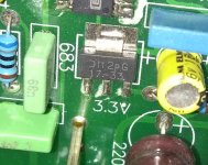
By identify it you mean tell you the manufacturer? No idea right now but the logo somehow looks familiar.
Yes, that's what I meant.
I would like to check the data sheet to see if the component values used are correct. But for that I need to know the part name !
I would like to check the data sheet to see if the component values used are correct. But for that I need to know the part name !
Hi
i am on the same way with my dac expereince 😉
https://www.diyaudio.com/forums/digital-line-level/334312-cm6631a-es9023-cheap-board-modification.html#post5718346
actually nobody is interesting...😉
but i found that the values are too high according to the datasheet....i found the relevant information on the NCP 1117 datasheet...not in the ams 1117 datasheet
A 10 F ceramic or tantalum capacitor should be adequate for most applications. Frequency compensation for the regulator is provided by
capacitor Cout and its use is mandatory to ensure output stability. A minimum capacitance value of 4.7 F with an equivalent series resistance (ESR) that is within the limits of 33 m (typ) to 2.2 is required. See Figures 12 and 13. The capacitor type can be ceramic, tantalum, or aluminum electrolytic as long as it meets the minimum capacitance value and ESR limits over the circuit’s entire operating temperature range. Higher values of output capacitance can be used to enhance loop stability and transient response with the additional benefit of reducing output noise.
i am not an expert but i think to measure with scope and try some caps should be the correct way if you move away from datasheet specs (bigger caps on Cout)
chris
Last edited:
....
If you just do a full replacement without knowing what is going on, you may find later that you used the wrong part for the job.
.....
Maybe reread the thread and make some notes, should be enough in there to get the sss sounds to be good, or much better anyways. Is what I have done over the course of a few years to several dacs.
......r.

i do this for all my nooby mod´s....
Yes, I have found that data sheet but since I was not about the identity of the chip, I haven't compared it with the actual values vs data sheet values.
I should be inspecting the PCB more as I think the designer who did the pcb layout and components selection made some differing choices compared to that of the data sheet recommendations.
I should be inspecting the PCB more as I think the designer who did the pcb layout and components selection made some differing choices compared to that of the data sheet recommendations.
Good that you are having a look at the board and the details.
Also on the regulator data sheets, they may be showing that a certain, small ceramic capacitor will be stable in an effort to appeal to prospective customers who do not want to have to use any more components in their product than is absolutely necessary.
You need to try some different parts after the regulator until you are happy with it, while maintaining the suggested esr values, or watching with a scope for added noise/instability.
Hmm, interesting thought. So, a higher capacity cap than necessary can be a good thing ?
I don't have a scope 🙁
I don't have a scope 🙁
Just have to watch the esr of the cap you use, and be sure you are within the range that is recommended.
I am using some fairly standard ones that are 100uf 25v on the ams1117 that are in a digital player. They do need to be within 10mm of the regulator.
I tend to learn more by doing, so in turn, I must reread things a few times myself.
I am using some fairly standard ones that are 100uf 25v on the ams1117 that are in a digital player. They do need to be within 10mm of the regulator.
I tend to learn more by doing, so in turn, I must reread things a few times myself.
Thanks for the comment Phase. But why 25V ? As the voltage goes up, doesn't the ESR increase ?
BTW, I did a google search and came across some interesting discussion on the 7805 regulator. See this link Which capacitors for L7805 regulator? See the post number 5 by 'arduinoaleman' It answers all of my doubts.
So, a 220uF electrolytic (Nichicon UKA ? or Panasonic FM) + 0.1uF ceramic X7R at input and 100uF electrolytic (Nichicon UKA or Panasonic FM)+0.1uF ceramic X7R at output !
An after thought !
A 220uF and 100 uF caps are not small and when I turn off the dac, wouldn't they discharge through the regulator ? Would it cause any issue ?
Reality check:
When set about modding this DAC, I never thought it could be this complex lol😀
Low ESR caps cause resonances in some places, Ceramic & Tantalum caps have weird behavior, electrolytic caps if used well below the rated voltage exhibits different properties, some regulators have high tolerance for ESR values of caps while some don't, longer traces means more parasitic inductance, DAC chips have 'poor' PSRR and power supply characteristics can affect their performance ......need a meticulous approach to design a good circuit, doesn't it ?
I'm thinking right now that I have bitten more than I can chew lol 😀
So, I have to set a deadline for all this because I cannot let this take away my free time for ever!
Posting my question here as I am wondering best way to power DAC in my cd player a Marantz CD 48 with a Philips TDA1549 DAC.
The cap before the 7805 got upgraded from a 4700µF/16V to a Panasonic FM 8200µF/16.
Between the 7805 and the 3 inputs (VDDD,VDDA,VDDO) there were for each input a standard looking elko 47µF/25V these I have replaced with a 220uF 25V FG Nichicon each.
So thats the current situation. Wondering how to proceed next. Since each input has its own cap now i dont know how much benefit ill have to add a cap right onto the 7805 output itself, maybe for the other components that depend on it. Input wise maybe i can add a ceramic 100nf cap on the 7805.
For the DAC itself there are for those 3 inputs also 100nf caps in paralel that were there stock next to the 3 new Nichicon caps. I wondered if i should remove those and add a film ( cause ceramic has microphonic side effects though its not on a digital or analog audio signal ) 100nf WIMA cap for each input right onto the pins of the DAC instead.
All new to me and read several opinions, maybe you guys can provide some input. My main thread can be found here My first project : Marantz CD 48 disc not spinning
Myself, I would definitely have the small ceramic decoupling at the dac chip, I do not have that on or near the regulators however. I use a snubber on the diodes just ahead of that.
You’re going to be safe using a standard 47-100uf part on the output side, and the esr lowers with an increase in voltage typically. That Fm should work well on the input side.
I wouldn’t recommend film capacitors in the positions near a dac chip, however, I don’t have any specific experience with that CD player either. I would search for threads discussing that chip, or even that model of player to get a less general answer.
- Home
- Source & Line
- Digital Line Level
- Cheap chi-fi DAC buy (<30 USD)