Received my ADAU1466 board today, the transistor is flipped over also. Must be correct so, wrong PCB footprint used during board design.
I'm a little bit overwhelmed by the plus on options compared to a ADAU1701 in SigmaStudio 😉
I'm a little bit overwhelmed by the plus on options compared to a ADAU1701 in SigmaStudio 😉
Hey guys, just an update - I received my ADAU1452 board and the USBI from Tindie, and everything looks fine. But I haven't had time to play with it yet, as I must prepare extra 2 channels of amplification and DAC before I can hook it all up.
Currently finishing the Arduino powered DC Load from this gentleman:
YouTube
Boy this diy can really get out of hand... 🙂
Currently finishing the Arduino powered DC Load from this gentleman:
YouTube
Boy this diy can really get out of hand... 🙂
Hi Guys,
Great thread. Seems like a great idea.
But may a novice ask a question??
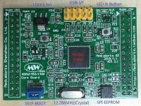
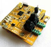
It would seem that eBay have 2 types of 1452 Board – the green one and the yellow one. If I wanted to incorporate it into a BALANCED (XLR), which one would you suggest??
Great thread. Seems like a great idea.
But may a novice ask a question??
It would seem that eBay have 2 types of 1452 Board – the green one and the yellow one. If I wanted to incorporate it into a BALANCED (XLR), which one would you suggest??
If I wanted to incorporate it into a BALANCED (XLR), which one would you suggest??
What do you mean by that? Seems unlikely you would want to put a DSP chip inside an XLR connector but one never knows around here.
Hi Markw4
Thanks for the reply.
No I did not mean to put the chip in the XLR. I just wanted to state that my entire system is balanced using XLR. As most people have single ended and use RCA.
I also forgot to attach the photos of the boards.
It will be a fun and steep learning curve.
D
Edit – My apologies. I re-read the entire thread and the Green Board is the go with a Tindie SingmaLink USBi.
As I am a total novice, any other ready-made boards, connectors that are available?
Thank you
D
Attachments
Last edited:
Hooking up ADAU1452 to USB receiver and two AK4490 DACs
Hi guys, just wanted to revive the thread a bit.
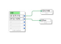
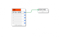
I got my ADAU1452 board working in SPI mode, I couldn't get it to run in I2C mode, but maybe I just messed up something. Anyway, it's working fine over SPI 0x1 Adr0, still didn't try the EEPROM.
At first when I connected my USB receiver (diyinhk isolated 768khz) I wasn't getting the I2S signal, and there seemed to be some kind of voltage over the GND pin because the DSP board LED wouldn't turn off all the way when I shut it down in SigmaStudio. At some point I disconnected the GND pin and it all started working, even with the GND pin back on. Weird, might have been some kind of ground loop or something.
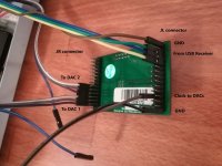
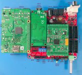
Now to share some insight for those who encounter these problems: I have a USB receiver with it's own clock, and two AK4490 DACs that can't work without a master clock (MCLK) provided externally. I connected the I2S signal from the receiver and the two DACs like you can see in the photo, also note the JL pin 24 (ADAU clock out) and GND pin go to both DACs. That's not all, I had to go to ADAU1452 Register Controls tab in SigmaStudio, then Serial Ports tab and change the SDATA_IN0 settings: LRCLK Source and BCLK Source to "Slave from CLK domain 0", and then I got the signal through.
Also the first DAC is on channels 0 and 1, but I found the second one is on 16 and 17, because each bus (group) on the ADAU1452 has 16 channels (starting from 0).
This was some trial and error because I couldn't find a lot of info about I2S signal in the ADAU documentation. Will do some more investigating on different ways to use the clock, as I want to use the Ian's McFIFO both for reclocking the signal from USB receiver to DSP and from DSP to the two DACs.
On a sidenote, I'm controlling the DACs with an Arduino loaded with modified code that DimDim wrote.
This is going to be the digital crossover/EQ for my LX mini setup 🙂
Hi guys, just wanted to revive the thread a bit.
I got my ADAU1452 board working in SPI mode, I couldn't get it to run in I2C mode, but maybe I just messed up something. Anyway, it's working fine over SPI 0x1 Adr0, still didn't try the EEPROM.
At first when I connected my USB receiver (diyinhk isolated 768khz) I wasn't getting the I2S signal, and there seemed to be some kind of voltage over the GND pin because the DSP board LED wouldn't turn off all the way when I shut it down in SigmaStudio. At some point I disconnected the GND pin and it all started working, even with the GND pin back on. Weird, might have been some kind of ground loop or something.
Now to share some insight for those who encounter these problems: I have a USB receiver with it's own clock, and two AK4490 DACs that can't work without a master clock (MCLK) provided externally. I connected the I2S signal from the receiver and the two DACs like you can see in the photo, also note the JL pin 24 (ADAU clock out) and GND pin go to both DACs. That's not all, I had to go to ADAU1452 Register Controls tab in SigmaStudio, then Serial Ports tab and change the SDATA_IN0 settings: LRCLK Source and BCLK Source to "Slave from CLK domain 0", and then I got the signal through.
Also the first DAC is on channels 0 and 1, but I found the second one is on 16 and 17, because each bus (group) on the ADAU1452 has 16 channels (starting from 0).
This was some trial and error because I couldn't find a lot of info about I2S signal in the ADAU documentation. Will do some more investigating on different ways to use the clock, as I want to use the Ian's McFIFO both for reclocking the signal from USB receiver to DSP and from DSP to the two DACs.
On a sidenote, I'm controlling the DACs with an Arduino loaded with modified code that DimDim wrote.
This is going to be the digital crossover/EQ for my LX mini setup 🙂
Attachments
Last edited:
Hi, I am using the ADAU1452 from Aliexpress with my FreeUSBi, and managed to compile and download (I am not getting any error) and it seems to work because every time I press F7 I hear a "bip" and the blue led lights up a few times... the thing is I am not getting any sound!!
I am using analog inputs/outputs without any sound.
Any help would be greatly appreciated
Cheers
I am using analog inputs/outputs without any sound.
Any help would be greatly appreciated
Cheers
You have to give more info as it is a very complex system. Please try the Analog devices Engineer zone first at ez.analog.com and search for ADAU1452 for basic setup.
My thread about the crossover and advanced settings is here.
But also if your board has analog inputs and outputs it is not the same as mine, so there will be differences in setup.
My thread about the crossover and advanced settings is here.
But also if your board has analog inputs and outputs it is not the same as mine, so there will be differences in setup.
You have to give more info as it is a very complex system. Please try the Analog devices Engineer zone first at ez.analog.com and search for ADAU1452 for basic setup.
My thread about the crossover and advanced settings is here.
But also if your board has analog inputs and outputs it is not the same as mine, so there will be differences in setup.
Thanks for your reply!
I finally found how to output sound from the analog outputs. I requested the seller for the Sigma Studio schematics of the default program, so I started from there, removing non essential parts for me.
Of course I am very far from perfect, even far from good, but I least I have sound, tested crossover, PEQ, etc.
I will check the Sigma's forum for more in depth information!
Glad I could help. ADAU1452 is an incredibly powerful processor, but to get anything advanced from it you need to learn Sigma Studio step by step. Analog Engineer zone is a great place to learn, and Dave Thib is the man 🙂
Hi All,
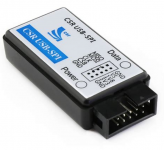
I cannot get Sigma Studios to recognize my ADAU1452 using a CSR USB to SPI converter with the Analog Devices drivers installed on it.
Does the ADAU1452 require the use of the EVAL-ADUSB2EBUZ to program? or will any USB -> SPI converter work? Is there something special about the Analog Devices converter that I am missing?
Any help would be great!
Attachments
I am currently playing with an ADAU1452 and Sigma Studio. It is very impressive all the things it can do. But there is a problem I have found.
The filters for crossover are based on the bilinear transform, so the phase linearity of the analog prototype is not preserved after the transformation due to frequency warping. Does anyone know how to get around this to preserve linear phase?
Here is where the Analog Devices representative confirms this

Member
Joined 2018
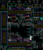
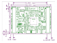
Can anyone who has this module please measure the distance shown in pink, using calipers?
Here's a pic of the pin spacing marked onto perboard, half a bloomin hole out so designed around .127" pitch. I bent pins on female headers to adapt to fit some perfboard.
Attachments

Here's a pic of the pin spacing marked onto perboard, half a bloomin hole out so designed around .127" pitch. I bent pins on female headers to adapt to fit some perfboard.
That's 20.5 spaces (from highest pin to lowest) at 2.54mm a pop means 52.07mm instead of 52.5mm.
Member
Joined 2018
- Home
- Source & Line
- Digital Line Level
- cheap aliexpress/eBay ADAU1452 development boards