Member
Joined 2018
Thank you!
Can you feed it 3.3V directly and a master clock to bypass the one it uses on board?
My design feeds 5V supply only. Removing U4 and supply 3.3V directly is good idea to prevent from the U4 over-heating risk. I will add this option for my next version board design.
Four output headers for DAC has buffered master clock output from the MW1466 JL-pin24. (To keep the better signal integrity)
CyberPit
Isn't MCLK on the input i2s signal connector?
I don't know if I'll add a usb receiver, I'll go for spdif at first and see later if I add usb. I'll breakout a connector for i2s input so I can later add one if I need it.
I don't know if I'll add a usb receiver, I'll go for spdif at first and see later if I add usb. I'll breakout a connector for i2s input so I can later add one if I need it.
Member
Joined 2018
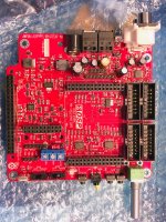
Here's my WM-ADAU1466 Breakeout Board Design Files
Now I will upload my MW-ADAU1666/1452 breakout board design information for this thread readers. This board has Pre-Amplifire like features as follows...
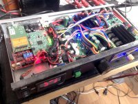
Second one is an application example. Its my full-digital connected TAS6422 4ch Amplifier.
Enjoy!
CyberPit
I would be interested in the other board you've showed in the other thread. From what I saw, it accomodates the ADAU1452/-66 chinese boards.
Any chance to get the gerber files?
Now I will upload my MW-ADAU1666/1452 breakout board design information for this thread readers. This board has Pre-Amplifire like features as follows...
- A DSP slot for MusicWorks MW-ADAU1466/1452 module
- Single DC12V power supply and embedded On-board power supply for all embedded Boards and Circuits
- Amaneo Combo384 Slot for USB-Audio Input
- MP6/MP7 GPIO Header for source selection.
- Header for AUX ADC
- Raspberry-Pi 40pin I2S Connection Slot
- Raspberry-Pi 40pin SPI interface for SigmaStudio's SPI over TCP/IP Connection. (TCPi)
- Auto delay Turn-On and Auto shutdown support power supply for Raspberry-Pi Automotive Application (RP4 Compatible)
- IR-Remote sensor for Raspberry-Pi
- IR-Transmitter LED for Raspberry-Pi
- 2 push buttons for Raspberry-Pi
- Breakout Header for Raspberry-Pi I2C
- Breakout Header for Raspberry-Pi UART
- Raspberry-Pi disable switch with keep hold-on features.
- 96kHz ADC for Analog Input
- Optical S/PDIF Input
- Optical S/PDIF Output
- Rotary Pot for AUX ADC
- 4times Buffered I2S Outputs
Second one is an application example. Its my full-digital connected TAS6422 4ch Amplifier.
Enjoy!
CyberPit
Attachments
Last edited:
Hi All,
I cannot get Sigma Studios to recognize my ADAU1452 using a CSR USB to SPI converter with the Analog Devices drivers installed on it.
Does the ADAU1452 require the use of the EVAL-ADUSB2EBUZ to program? or will any USB -> SPI converter work? Is there something special about the Analog Devices converter that I am missing?
Any help would be great!
ADAU1452 doesn't need the EVAL board to program, your CSR converter should do the job. I use this one and it works fine.
There was a problem with USB driver to make it work properly, I remember copying some files manually to make SigmaStudio recognize the board, but you will have to google it as I don't remember where I found that info.
But make sure you troubleshoot the basic things first: try turning the 8pin connector the right way; check if the LEDs on ADAU board light up or not; is your board set to power over usb or self-powered?
There is a resistor that you can desolder to make sure it powers on only via 30pin header and not over usb, check your manual. Also the self-boot should be set to off when programming I think. And sometimes it "wakes up" when you press the reset switch.
Hope this helps, it's a great board, although SigmaStudio can be daunting.
I am currently playing with an ADAU1452 and Sigma Studio. It is very impressive all the things it can do. But there is a problem I have found.
The filters for crossover are based on the bilinear transform, so the phase linearity of the analog prototype is not preserved after the transformation due to frequency warping. Does anyone know how to get around this to preserve linear phase?
Here is where the Analog Devices representative confirms this
This is very important info, thanks for sharing!
Don't know how much impact this has on the final sound but it can't be good. Right now I'm using IIR coefficients for crossover but was planning to recreate it using normal filters as IIR coeffs have to be recalculated for each samplerate.
Will look into this, but please share more if you can.
Hi,
I need soem guidance regarding my ADAU 1452 board.
I've got this board:
Buy Products Online from China Wholesalers at Aliexpress.com
I am quite happy with it as it works properly... but I am having the following problem. When I connect my DSP to my AMP and start programming crossovers for my speakers (CD and 6.5 pro audio woofer, so both are very sensitive) everything works OK, the DSP is quite silent and I can only hear a hiss coming thru the CD if I put my ear close to the waveguide, so great...
The thing is that after meddling a little with SigmaStudio and the integrated potentiometer (which I use as digital volume control), the DSP start to make a strong hiss thru my speakers... and the only way to fix it is to press F7 -download the scheme again to the DSP- (not writing the eeprom).
This happens if I power the DSP thru my latptop's USB and if I power it thru an external battery or wall wart. It makes no difference.
Could it be that the USBi (which is always connected to the DSP and my laptop thru USB) is messing with the DSP?
Also to consider is that I am using the analog inputs/outputs on my DSP. A few times I tried it with SPDIF input and I don't recall having the same issue.
Any help to determine where is the problem, would be great.
Cheers.
What configuration do you have? If it is set up to clock from the input S/PDIF without using ASRC and you are listening to an analogue input via the ADC then the DSP may not actually be running. Easiest test for this is to plug in a S/PDIF source signal and see if your ADC inputs then start to work.Hi,
I need soem guidance regarding my ADAU 1452 board.
I've got this board:
Buy Products Online from China Wholesalers at Aliexpress.com
I am quite happy with it as it works properly... but I am having the following problem. When I connect my DSP to my AMP and start programming crossovers for my speakers (CD and 6.5 pro audio woofer, so both are very sensitive) everything works OK, the DSP is quite silent and I can only hear a hiss coming thru the CD if I put my ear close to the waveguide, so great...
The thing is that after meddling a little with SigmaStudio and the integrated potentiometer (which I use as digital volume control), the DSP start to make a strong hiss thru my speakers... and the only way to fix it is to press F7 -download the scheme again to the DSP- (not writing the eeprom).
This happens if I power the DSP thru my latptop's USB and if I power it thru an external battery or wall wart. It makes no difference.
Could it be that the USBi (which is always connected to the DSP and my laptop thru USB) is messing with the DSP?
Also to consider is that I am using the analog inputs/outputs on my DSP. A few times I tried it with SPDIF input and I don't recall having the same issue.
Any help to determine where is the problem, would be great.
Cheers.
Everybody should be careful when working with SigmaStudio.
You could get loops that get full output on your speakers.
I know that the hard way.
Blown a tweeter and an OPA on my amp.
You could get loops that get full output on your speakers.
I know that the hard way.
Blown a tweeter and an OPA on my amp.
What configuration do you have? If it is set up to clock from the input S/PDIF without using ASRC and you are listening to an analogue input via the ADC then the DSP may not actually be running. Easiest test for this is to plug in a S/PDIF source signal and see if your ADC inputs then start to work.
I need to check that, but DSP is "always" running... I mean, if I use SDIF input or analog input, the DSP works, and XO works, gain, PEQ, etc.
The only annoying thing is sometimes the analog output gets noisy as hell (without changing the scheme), then rewrite with F7 and back to normal... silent and working OK.
I DO need to test if this happens also If I unplug the USBi and run only from the EEPROM.
Everybody should be careful when working with SigmaStudio.
You could get loops that get full output on your speakers.
I know that the hard way.
Blown a tweeter and an OPA on my amp.
Totally agree with you. If I am changing something in the scheme that it's not meant to be modified "on the fly", I switch my amplifiers off and then modify the scheme... PEQ is particularly dangerous and sometimes it gets a loud bump.
If you place a mute block just before the output and toggle it in SigmaStudio when the noise is happening, does it have any effect? Keep an eye out in the bottom righthand corner to check for a communications fail.I need to check that, but DSP is "always" running... I mean, if I use SDIF input or analog input, the DSP works, and XO works, gain, PEQ, etc.
The only annoying thing is sometimes the analog output gets noisy as hell (without changing the scheme), then rewrite with F7 and back to normal... silent and working OK.
I DO need to test if this happens also If I unplug the USBi and run only from the EEPROM.
Totally agree with you. If I am changing something in the scheme that it's not meant to be modified "on the fly", I switch my amplifiers off and then modify the scheme... PEQ is particularly dangerous and sometimes it gets a loud bump.
Dear All,
I am using a ADAU1452 board from mediaworks (green one) and it does work fine sofar.
I am using freeUSBI to programm with Sigmastuido.
The eeprom also worked eventually. I got it working if programmed via DSP and by reviewing the technical details of the eeprom.for a 25AA1024 ,programming using SPI3, the bitsize to be set to 1048576, page size 256, writespeed 10000 kHz and address bytes to 3.
I am using a raspi 3b+ with volumio to feed the DSP via I2S from there via I2S to 2 DACs. I am using the DSP as a 2 channel cross over. I had to choose Output 2 as second output, for some reason output 1 did not work ( LRCLK was always 0V )
I am now using output 0 and output 2. I have not a second board to check if my specific board has an issue or if this is a problem with the series. I cannot exclude I did oversee some conflicting sigmastudio setting neither 😉 .
As a next step I will further incorporate Ian's FIFOPI and want the masterclock to be the DSP clock.
hi, I'm using the black evaluation board form AliExpress and it works perfectly, spdif input, two DAC's using the serial output.
I wonder if some body have the usb drive for windows to stream audio from my pc to the board, Windows tries to install a serial port but it did't find the drivers
I wonder if some body have the usb drive for windows to stream audio from my pc to the board, Windows tries to install a serial port but it did't find the drivers
I'm thinking of getting an ADAU1452 board like this one Lusya ADAU1452_DSP Development Board Learning Moudle DSP Board With CODEC F9 006|Replacement Parts & Accessories| - AliExpress, with the codec board. I want to feed the board with a 192KHz SPDIF signal
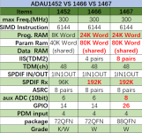
What I'm confused about, is that in other Aliexpress listings like this one SIGMADSP ADAU1452 / ADAU1466 core board (new)|Personal Care Appliance Parts| - AliExpress they have a table that says that the ADAU1452 only has a 96KHz SPDIF input, see attachment
The ADAU1452 datasheet mentions a half-clock speed version of the ADAU1452, but the only difference mentioned by the datasheet between the 1466 and 1452 is the memory size
Can someone with the ADAU1452 board with codecs please confirm that their ADAU1452 runs at 294.912 MHz (put it another way, it has to be version ADAU1462WBCPZ300, not ADAU1462WBCPZ150
Attachments
If you tell me where to look, I can check my Lusya ADAU1452 board with SPDIF input.
Thanks! It should be in the device markings. Here's a picture I found of an ADAU1467 with the full markings WBCPZ300.
If you could take a picture of the ADAU1452 in good light, I should be able to figure out if the markings provide the necessary info (or ask the Analog forum)
In reading this post ADAU1462-150 PLL and other settings - Q&A - SigmaDSP Processors and SigmaStudio Development Tool - EngineerZone and the datasheet, especially "Table 28. Optimal Predivider and Feedback Divider Settings for Varying Input MCLK Frequencies", it looks as if the 300 and 150 versions use the same settings, which are handled transparently by Sigmastudio and the chip, so it looks as if there is no way to tell from the Sigmastudio info what chip is being used
Attachments

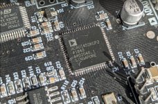
Here is the picture.
Hope it helps.
Perfect, thanks. looks like a 300MHz part (full speed), but I'll double check and get back to this post
I asked the Analog forums (How do I recognize an ADAU1452-150? - Q&A - SigmaDSP Processors and SigmaStudio Development Tool - EngineerZone) and I learned two things:
Has anyone here ever successfully used 192KHz S/PDIF in on the ADAU1542 board discussed here?
- The chip marked ADAU1452WBCPZ is the 300MHz part. the 150MHz version would be marked ADAU1452WBCPZ150
- The 1452 is only certified to work with 96KHz S/PDIF, and does not support 192KHz S/PDIF. The supported way to have 192KHz S/PDIF is either to use a S/PDIF to I2S converter or use the ADAU1462, which is pin and software compatible and works up to 192KHz
Has anyone here ever successfully used 192KHz S/PDIF in on the ADAU1542 board discussed here?
Does anyone know if this programmer is possible to use for the 1466? It's named: EVAL-ADUSB2EBUZ (which seem to be right) but it's also for a specific board named SigmaStudio ADSP21489 Development Board. Are these programmers programmed in it selves to suit specific boards only? Or are they generic?
The freeUSBi aren't possible to order right now due to the seller who's taking a break until december.
The freeUSBi aren't possible to order right now due to the seller who's taking a break until december.
The EVAL-ADUSB2EBUZ is identical to the EVAL-ADUSB2EBZ and will work with the ADAU1466. The "U" just means it is a University version sold at a cheaper price. The non-U version is disproportionally expensive at $95, especially as a complete evaluation package of an ADAU1466 board is $200 and includes the programmer!Does anyone know if this programmer is possible to use for the 1466? It's named: EVAL-ADUSB2EBUZ (which seem to be right) but it's also for a specific board named SigmaStudio ADSP21489 Development Board. Are these programmers programmed in it selves to suit specific boards only? Or are they generic?
The freeUSBi aren't possible to order right now due to the seller who's taking a break until december.
- Home
- Source & Line
- Digital Line Level
- cheap aliexpress/eBay ADAU1452 development boards