I have two of those, not particuarly reliable for some reason, but main reason is the ADAU1467 board I used is only about £6 dearer but a substantially more capable DSP. Twice the data memory, three times program memory, 12 input and 12 output serial ports, versus only 4 each for the '1452. The Mediaworx board is better made with same 10 pin programming header that Analog Devices use on their evaluation kits.
Do you have more info on the Mediawork 1467? You bought it in Aliexpress? Also needs CODEC AD1933?I have two of those, not particuarly reliable for some reason, but main reason is the ADAU1467 board I used is only about £6 dearer but a substantially more capable DSP. Twice the data memory, three times program memory, 12 input and 12 output serial ports, versus only 4 each for the '1452. The Mediaworx board is better made with same 10 pin programming header that Analog Devices use on their evaluation kits.
Also, are you planning on open sourcing your PCB?
If you search on "ADAU1467 DSP Core board" you will find it. They do a motherboard with CODEC but a lot more expensive and I wanted to use the TI PCM1795 DACs which are superior to the AD CODECs and also wanted differential balanced outputs. If you only want to use the AD codec designs then no real need to use the board I designed.
I had not planned on open sourcing it as it is customised to my specific requirements, but happy to share the pcb design files (created in Diptrace) if someone wants to take it on and make it more generic. I did not bother with a schematic for this one, went straight to pcb layout. A couple of pages back in post #76 I uploaded a block diagram in case you missed it.
I had not planned on open sourcing it as it is customised to my specific requirements, but happy to share the pcb design files (created in Diptrace) if someone wants to take it on and make it more generic. I did not bother with a schematic for this one, went straight to pcb layout. A couple of pages back in post #76 I uploaded a block diagram in case you missed it.

Thanks so much for sharing your work, really inspiring!If you search on "ADAU1467 DSP Core board" you will find it. They do a motherboard with CODEC but a lot more expensive and I wanted to use the TI PCM1795 DACs which are superior to the AD CODECs and also wanted differential balanced outputs. If you only want to use the AD codec designs then no real need to use the board I designed.
I had not planned on open sourcing it as it is customised to my specific requirements, but happy to share the pcb design files (created in Diptrace) if someone wants to take it on and make it more generic. I did not bother with a schematic for this one, went straight to pcb layout. A couple of pages back in post #76 I uploaded a block diagram in case you missed it.
Could you confirm the number of FIR taps you are able to do with the core board? Or could you give the details for the settings in the hardware section so I can estimate it with how I would setup the DSP? Trying to figure out how much these can do for a project.If you search on "ADAU1467 DSP Core board" you will find it. They do a motherboard with CODEC but a lot more expensive and I wanted to use the TI PCM1795 DACs which are superior to the AD CODECs and also wanted differential balanced outputs. If you only want to use the AD codec designs then no real need to use the board I designed.
I had not planned on open sourcing it as it is customised to my specific requirements, but happy to share the pcb design files (created in Diptrace) if someone wants to take it on and make it more generic. I did not bother with a schematic for this one, went straight to pcb layout. A couple of pages back in post #76 I uploaded a block diagram in case you missed it.
Not sure I fully understand your question. I'm not using FIR filters, I would guess the limitation will depend on how much DSP memory is available which in turn will depend on the complete design for your project.Could you confirm the number of FIR taps you are able to do with the core board? Or could you give the details for the settings in the hardware section so I can estimate it with how I would setup the DSP? Trying to figure out how much these can do for a project.
Precisely. I am weighing whether this would be a worthwhile upgrade from the cheap ADSP-21489 boards I have (with pcm1798 DACs and PCM4202 ADCs) which can only achieve 4400taps with my current design. Also to know for any other future speaker project (I'm integrating the DSPs into custom plate amps for active speakers, so one board per speaker).Not sure I fully understand your question. I'm not using FIR filters, I would guess the limitation will depend on how much DSP memory is available which in turn will depend on the complete design for your project.
As such, the PEQ per driver and the overall PEQ, along with active crossover, noise gate, etc. are fine. It is mainly looking to do phase correction for the speaker and trying to find out what the maximum these can do.
And it is absolutely dependent on the memory available. This is why I was wondering if I could get the needed hardware settings page information (just a screenshot to mimic the settings in sigmastudio should be sufficient) or of you could just create a simple one that splits with a 3-way crossover then throw in FIR filters for each (either three or four), then just increase them until it says it cannot compile due to memory. That should give more info, as many are interested in which to get.
The aliexpress ADSP-21489 is more limited on memory than many hoped for, so if these can do more taps, that would be worth knowing for the community.
Precisely. I am weighing whether this would be a worthwhile upgrade from the cheap ADSP-21489 boards I have (with pcm1798 DACs and PCM4202 ADCs) which can only achieve 4400taps with my current design. Also to know for any other future speaker project (I'm integrating the DSPs into custom plate amps for active speakers, so one board per speaker).
As such, the PEQ per driver and the overall PEQ, along with active crossover, noise gate, etc. are fine. It is mainly looking to do phase correction for the speaker and trying to find out what the maximum these can do.
And it is absolutely dependent on the memory available. This is why I was wondering if I could get the needed hardware settings page information (just a screenshot to mimic the settings in sigmastudio should be sufficient) or of you could just create a simple one that splits with a 3-way crossover then throw in FIR filters for each (either three or four), then just increase them until it says it cannot compile due to memory. That should give more info, as many are interested in which to get.
The aliexpress ADSP-21489 is more limited on memory than many hoped for, so if these can do more taps, that would be worth knowing for the community.
One potential solution is a USB Interface (most of them have much better performance than Aliexpress's DSP boards, especially in ADC) + RaspberryPi + CamillaDSP.
I've read the processing potential is bigger on the raspberry than the DSP
Yes, I've played with the RPi4. Way more FIR taps are possible. When I was experimenting with that, the simple ADAU1701 sure boards could not do both digital out and in in a way to sandwich and offload the processing over to the RPI and back.One potential solution is a USB Interface (most of them have much better performance than Aliexpress's DSP boards, especially in ADC) + RaspberryPi + CamillaDSP.
I've read the processing potential is bigger on the raspberry than the DSP
But I haven't looked at trying to do a digital out and in on the 21489 boards yet.
RPi takes more effort to get setup and I would have to hang all sorts of things off of it. Instead, I went with an Arylic Up2Stream Pro v3 feeding to the 21489 boards which then feed to the amplifiers on a per channel basis for each driver.
I might return to the RPi as a stand alone or integrated to boost the processing of FIR filtering in the future. But this project is so far along now, I likely won't change again at this moment. Maybe for the ADAU1467, but generally I'd just like to know which ones to recommend for which purposes.
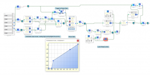
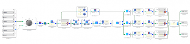
So, my design is basically a combination between the two sigmastudio pics below. I recently reinstalled windows, so don't have CCES or sigmastudio setup yet to get a clean pic here. I'm still playing with the designs.
Obviously I cannot use that many FIR taps on the boards I have currently. So please ignore the exact settings and instead look at the schematic generally. It has time and sensitivity alignment, PEQs overall and per driver basis, infrasonic filter/low end excursion filter, with the cascading butterworths being an LR filter. It then uses the FIR to correct around the crossover points and FIR correction on the per driver PEQ and to address phase shifts from the amplifier. But these schematics are not finalized yet.
Obviously I cannot use that many FIR taps on the boards I have currently. So please ignore the exact settings and instead look at the schematic generally. It has time and sensitivity alignment, PEQs overall and per driver basis, infrasonic filter/low end excursion filter, with the cascading butterworths being an LR filter. It then uses the FIR to correct around the crossover points and FIR correction on the per driver PEQ and to address phase shifts from the amplifier. But these schematics are not finalized yet.
Attachments
I do not think this question relates to the board, but to the ADAU1467 DSP, so can you not create your own project in SigmaStudio for the '1467 and compile it?Precisely. I am weighing whether this would be a worthwhile upgrade from the cheap ADSP-21489 boards I have (with pcm1798 DACs and PCM4202 ADCs) which can only achieve 4400taps with my current design. Also to know for any other future speaker project (I'm integrating the DSPs into custom plate amps for active speakers, so one board per speaker).
As such, the PEQ per driver and the overall PEQ, along with active crossover, noise gate, etc. are fine. It is mainly looking to do phase correction for the speaker and trying to find out what the maximum these can do.
And it is absolutely dependent on the memory available. This is why I was wondering if I could get the needed hardware settings page information (just a screenshot to mimic the settings in sigmastudio should be sufficient) or of you could just create a simple one that splits with a 3-way crossover then throw in FIR filters for each (either three or four), then just increase them until it says it cannot compile due to memory. That should give more info, as many are interested in which to get.
The aliexpress ADSP-21489 is more limited on memory than many hoped for, so if these can do more taps, that would be worth knowing for the community.
Got ya, brain fart assuming these may, like the 21489, support external memory. Just double checked the spec sheet for the adau1467. My bad.I do not think this question relates to the board, but to the ADAU1467 DSP, so can you not create your own project in SigmaStudio for the '1467 and compile it?
When doing an extremely simple layout, 23500 taps on three groupings is what I got with it still running real time.
Looks like you tried it for the '1452 board, the board I used has the '1467 which is a lot more capable.Got ya, brain fart assuming these may, like the 21489, support external memory. Just double checked the spec sheet for the adau1467. My bad.
When doing an extremely simple layout, 23500 taps on three groupings is what I got with it still running real time.
View attachment 1078383
View attachment 1078384
OK, if maxing out, you get closer to 32500 taps, but that is at 135% Inst cycles.Looks like you tried it for the '1452 board, the board I used has the '1467 which is a lot more capable.
The reason I don't want to kick it too much above 100% is I don't know the behavior on how much of a delay it adds. If just using speakers to play music, it is fine, but if watching TV or movies, the lip sync delay only allows for so much to match the audio. That was my concern and why I limited the taps to keep it to 100%, roughly. But you are correct, it can do more than that amount.
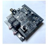
I got this https://www.aliexpress.com/item/1005002162173435.html adau1467 board from aliexpress (midiworx/mediaworx) and I got problem connecting 8ch dac (ES9016).
I have connected first 2 channels of dac to Serial out #0 of dsp and that works okay. Problem is with rest of channels and I want to use I2s, not TDM.
As I understand first i2s is going from serial out (as is connected now, and working) and rest of channels going from SDATAIO which I set like this:


Is it how it should be? Anything else to set in other tabs?
I have connected first 2 channels of dac to Serial out #0 of dsp and that works okay. Problem is with rest of channels and I want to use I2s, not TDM.
As I understand first i2s is going from serial out (as is connected now, and working) and rest of channels going from SDATAIO which I set like this:
Is it how it should be? Anything else to set in other tabs?
- Home
- Source & Line
- Digital Line Level
- cheap aliexpress/eBay ADAU1452 development boards