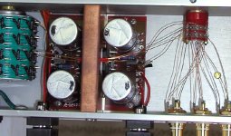
The wires from the switch to the pot should go through the hole above the chip (in copper piece). In that way they shouldn't pick any EMF. There is also another hole for alternative wire routing.
The best way to run wires from RCAs to the switch is without side panels attached, the access is better then. After you wire switch and the pot, you can add the sides , install rect board and run PS wires. The easiest way is to solder the ends to amp's board first (you have to put it through the middle panel hole before that), check how long it needs to be (to reach the rect board), cut and solder to rect board. Do that way all the 8 pcs.
If anybody has problems with locating the fuses, drop me a note and I'll send them to you. But don't be surprised to see 5A rating, as that's the minimum I'm using😉.
Attachments
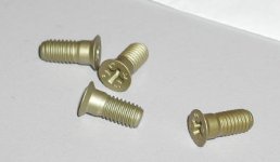
Jamh said:\ A quick question: what size screws are needed for the feet?
M6 x 1.
But if you want to use SAE, you could easily retap it to 1/4".
The pot looks like Noble.
Tony D. said:Hi Jamh,
What volume pot. is that you are using?
Thanks.
T.D.
As said above, it is a 20K Nobel. I'm using it in a shunt mode. Pinout is:
1. cut off
2. ground
3. output, also input with the 80k inline.
4. cut off
Peter,
The chassis can today and the build was of the quality expected, great job!!
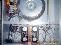
Only problem I have found is that my transformer is about .05" too tall to fit in the case. It is a 400VA Plitron, which if I recall from discussions well back on this thread, should fit. I guess there must be some variation between samples.
The chassis can today and the build was of the quality expected, great job!!
Only problem I have found is that my transformer is about .05" too tall to fit in the case. It is a 400VA Plitron, which if I recall from discussions well back on this thread, should fit. I guess there must be some variation between samples.
Recently, I also had 400VA Plitron that was just a hair too tall. You might replace the rubber washer for a thinner one and hopefully this should fix the problem.
Peter,
The 400VA is to large even without the gasket! It’s probably not a good idea to recommend the 400VA version with your chassis, the tolerances are just too tight.
The 400VA is to large even without the gasket! It’s probably not a good idea to recommend the 400VA version with your chassis, the tolerances are just too tight.
The solutions I can think of is either sending you a new top cover with millout for bigger trafo, or exchanging your 400VA for one of mine 300VA units. Probably the first solution is better, I just have to figure out convenient method to do it.
Hi Peter,
I just got my kit today, and was giving a quick going over. I think I am missing the screws that attach the bottom to the inside piece that goes across the body. No biggie, can go to my local HW store and pick them up.
But, I was wondering (if its is not already done, I must admit I did not search through 72 pages of this thread) if you could post a list of the included HW. It would help people (like me) make sure they have all the right HW, and let them know what to get if they are missing something.
BTW, it looks very nice.
Anybody going to stain the sides? I am considering it, I think it would inprove the WAF, would match my furniture better.
Thanks,
Randy
Peter Daniel said:My Mom was sorting the hardware. She was very careful and I can't believe she made a mistake😉
There are 4 screws for attaching top and bottom panels (#10-32). If you are missing them, I'll send you some.
Sorry, I was confused. 😕
Looked in the bag again, and saw the screws in your pic. I thought I checked all the screws, don't know how I mess up.
Randy
Peter,
Milling out the top seems like a good idea. According to the Plitron web site. The specs. for the 400VA are 125mm (4.92") by 66mm (2.598"). With my rather crude T square measurement the trans. appears to be almost 2.6"" at its max hight with the gasket. Since the hight available in the chassis for the trans is 2.5", it looks like a little over .1" will do the trick.
Milling out the top seems like a good idea. According to the Plitron web site. The specs. for the 400VA are 125mm (4.92") by 66mm (2.598"). With my rather crude T square measurement the trans. appears to be almost 2.6"" at its max hight with the gasket. Since the hight available in the chassis for the trans is 2.5", it looks like a little over .1" will do the trick.
I assume the resistor for the led is in series, but I haven't seen any specifics on how it is hooked up (it's a very long thread and I could well have missed it). Across the dc output of the power supply?
Sheldon
Sheldon
Pobably the best way is to connect the LED wires across the small cap on rectifier's board (C2). Longer lead (n LED)goes through series resistor to + on a cap (I choose anything aroung 68K for resistor) and the shorter lead connects to the other side of the cap. Do it before installing rect board as otherwise access will be difficult.
How about winding some magnet wire around the toroid a couple of times to power the led? I think I have seen you do it a couple of times, but never got any specifics. Do you just need a resistor and the led? Or do you still need a diode or capacitor?Peter Daniel said:Pobably the best way is to connect the LED wires across the small cap on rectifier's board (C2). Longer lead (n LED)goes through series resistor to + on a cap (I choose anything aroung 68K for resistor) and the shorter lead connects to the other side of the cap. Do it before installing rect board as otherwise access will be difficult.
--Ferdi
That will work too, especially with toroids that are not potted and as few as 10 turns may be fine. Basically you don't need anything except the LED, but it may be more elegant to connect it through the diode. Depending on number of turns and produced voltage the resistor might not be needed, neither the cap. You need about 1.5V on red LED.
In a previous post I should rather say: "Probably the easiest way" because winding separate turns for LED is a better choice, IMO.😉
In a previous post I should rather say: "Probably the easiest way" because winding separate turns for LED is a better choice, IMO.😉
- Status
- Not open for further replies.
- Home
- Amplifiers
- Chip Amps
- Chassis for a group order of non-inverted GC kit?