The chassis arrived yesterday.
The quality and fit of the parts is simply marvellous
Thank You Peter !
The quality and fit of the parts is simply marvellous
Thank You Peter !
Pics now
Hi All-
Well thanks to some kind forum members I have the picture of my chassis reduced. I have several more pictures if anyone needs them.
Email is "stgrab@yahoo.com"
Thanks,
Troy
Original email below:
"Hi All-
I had the following chassis made for my CG.
I needed 3 chassis but my machinist told me the price difference between 3 and 10 were minimal so I had 11 made. 3 for me and 8 for anyone else who needs one.
I am NOT a business, so if ANY profit is made from these 8 it will be donated to this site.
Thanks,
Troy"
Attachments
We demand more pics- of the front, etc. and some kind of Price!!!!
-The Union Of Concerned Case Buyers
-The Union Of Concerned Case Buyers
Duuuude. Chill.
Variac the Destroyer-
Man relax a bit, your so agitated your gonna raise my blood pressure.
I took a few pictures yesterday but all of the files are over a Meg so I can't load them on the site.
Hi All-
I can email them one at a time to anyone who would be willing to host them for a few days/weeks.
The chassis cost me $75 each for material and labor from Arrowfab here in Dallas to make, I paid $50 for all of them to be "etched and clear hard anodized", and I just ordered $80 worth of Aluminum button head Allen wrench screws to put them together (300 screws!).
I am still looking for the "points or feet" I want to put under them.
I had these built to pay tribute to and RESEMBLE my Jeff Rowland Model 2 amp. I will most likely design another case that stands vertically like the Red Rose integrated so relax, many more to come in all types of shapes and sizes.
This is a hobby and I am VERY fortunate to have so many different shops and businesses in the DFW area to have just about anything made economically.
Back to the chassis at hand.
I have 8 to sell at cost + 10% for this website.
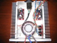
They are 8.5" wide x 2.5" tall x 8.5" long/deep. Internal is 2.25" tall, 5 3/8ths " wide, and 7 7/8ths " long/deep. Etched and hard clear anodized to show the aluminum. The front panel is 1/2" thick, the rest is 1/8th" thick.
If used as a stereo or mono amp it will fit everything needed. If used with a separate pwr supply enclosure it can fit 4 of BrianGT's boards mounted conventionally or 8(!) mounted unconventionally (half mounted normally, half inverted).
I am assembling mine now for the final pictures and listening tests.
Thanks again and happy building!
Troy
Variac the Destroyer-
Man relax a bit, your so agitated your gonna raise my blood pressure.
I took a few pictures yesterday but all of the files are over a Meg so I can't load them on the site.
Hi All-
I can email them one at a time to anyone who would be willing to host them for a few days/weeks.
The chassis cost me $75 each for material and labor from Arrowfab here in Dallas to make, I paid $50 for all of them to be "etched and clear hard anodized", and I just ordered $80 worth of Aluminum button head Allen wrench screws to put them together (300 screws!).
I am still looking for the "points or feet" I want to put under them.
I had these built to pay tribute to and RESEMBLE my Jeff Rowland Model 2 amp. I will most likely design another case that stands vertically like the Red Rose integrated so relax, many more to come in all types of shapes and sizes.
This is a hobby and I am VERY fortunate to have so many different shops and businesses in the DFW area to have just about anything made economically.
Back to the chassis at hand.
I have 8 to sell at cost + 10% for this website.
They are 8.5" wide x 2.5" tall x 8.5" long/deep. Internal is 2.25" tall, 5 3/8ths " wide, and 7 7/8ths " long/deep. Etched and hard clear anodized to show the aluminum. The front panel is 1/2" thick, the rest is 1/8th" thick.
If used as a stereo or mono amp it will fit everything needed. If used with a separate pwr supply enclosure it can fit 4 of BrianGT's boards mounted conventionally or 8(!) mounted unconventionally (half mounted normally, half inverted).
I am assembling mine now for the final pictures and listening tests.
Thanks again and happy building!
Troy
More pictures can be seen here curtsey of BrianGT:
http://brian.prohosting.com/pics/troy1.jpg
http://brian.prohosting.com/pics/troy2.jpg
http://brian.prohosting.com/pics/troy3.jpg
http://brian.prohosting.com/pics/troy4.jpg
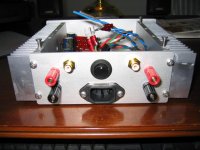
I have attached a picture of the rear I just assembled. I know, inexpensive binding posts, but this IS a proto-type. 🙂
Thanks,
Troy
http://brian.prohosting.com/pics/troy1.jpg
http://brian.prohosting.com/pics/troy2.jpg
http://brian.prohosting.com/pics/troy3.jpg
http://brian.prohosting.com/pics/troy4.jpg
I have attached a picture of the rear I just assembled. I know, inexpensive binding posts, but this IS a proto-type. 🙂
Thanks,
Troy
Attachments
Hey, you know I'm kidding!😉
Surprisingly, there is no Union of Concerned Case Buyers
Here is a decent sale on spikes. I got some and they are very well made. Choice of 4 colors:
http://www.partsexpress.com/webpage.cfm?&Webpage_ID=3&DID=7&CAT_ID=48&ObjectGroup_ID=139&SO=2
Did you get your power switch from Apex jr?
Surprisingly, there is no Union of Concerned Case Buyers
Here is a decent sale on spikes. I got some and they are very well made. Choice of 4 colors:
http://www.partsexpress.com/webpage.cfm?&Webpage_ID=3&DID=7&CAT_ID=48&ObjectGroup_ID=139&SO=2
Did you get your power switch from Apex jr?
Hey Variac-
I figured... I don't have high blood pressure either. 🙂
YES!!! Pwr switch, binding posts, IEC pwr input filter, Teflon insulated Silver coated copper wire, RCA's and transformer.
He is the whole reason I got into this. He told me he had LM3886 chips and I should build a CG.
Well I figured I would give them a listen with Brian's first then if I like it, make a kit for him to sell on his site using all his surplus parts so ANYONE could afford to build a CG.
I'm thinking a stereo CG with 3 LM3886 chips parralled on each side so it would do 50-60 wpc and be stable into 4 Ohms. Possibly even dual torids in a single chassis.
I ordered 25 of those switches and ACTUALLY had to rob this one from another project because I used all 25!
I will be calling him for more shortly.
Thanks,
Troy
Troy sent me some more pictures, and I put them on my website. I put them all on one page (11 images) to make it easier to see:
http://www.chipamp.com/troy/
(figured I would use this domain for something)
Alternately, you can view the images by going to:
http://www.chipamp.com/troy/troy01.JPG
to
http://www.chipamp.com/troy/troy11.JPG
--
Brian
http://www.chipamp.com/troy/
(figured I would use this domain for something)
Alternately, you can view the images by going to:
http://www.chipamp.com/troy/troy01.JPG
to
http://www.chipamp.com/troy/troy11.JPG
--
Brian
Question for Peter
Hey, Peter, do you have a timeframe for the next round of chassis?
I'm really eager to get one and I am wondering where and when you will announce the next group order for the integrated chassis.
Should I check the SpecializedKits webpage or the WIKI page or back on this thread?
"Enquiring minds want to know"
😀
Thanks,
-Erik.
I am not promoting the chassis anymore and the group purchase is finalized. I'm not planning on another one, as I was receiving too much critique from certain forum members.
I still have some chassis sets left and I'm planning on selling them as complete amps. However, if you are really in a need of that chassis, I can still sell some of those sets.
Since it is not a group buy anymore, I increased the price to $200/set as it's reflected on a website: http://www.specializedkits.com/groupbuy.html
I didn't update the site, but here's the current chassis appearance: http://www.diyaudio.com/forums/showthread.php?s=&threadid=37181&highlight=
Sign me up!
Peter,
Thanks for the info. Put me down for one right away! Would you like me to place the order through the Specialized Kits page?
Regarding all the criticism, pooh pooh to them. I think your work is terrific and offers a beginner a great place to start!
Let me know the details and I'll place my order right away.
Thanks very much, Peter.
Cheers,
-Erik.
Re: Sign me up!
I think that would be the most convenient way doing it.
e.lectronick said:Would you like me to place the order through the Specialized Kits page?
I think that would be the most convenient way doing it.
Peter Daniel said:
[snip]
Attach the wire to power the LED, before mounting rectifiers PCB, as later it's very hard. I'm using 68k resistor to provide voltage drop to the LED. The board doesn't have separate pads for that purpose (for some reason we didn't thought about it), so use your imagination.
[snip]
The Grayhill switch has to be adjusted for 4 position operation. There are two stop pins that had to be inserted in appropriate holes. One pin goes into the hole that is placed right at the groove (in threaded part of the bushing), second pins is placed 4 spaces clockwise (from first one).
There are 2 decks and two poles, so you can switch input and ground (for each channel) separately.
Last position can be connected to the signal ground and used for muting (without a need to turn off the pot).
[snip]
I did not provide the ground attachment point on the chassis, and it's up to you what to use. In one example, I just didn't provide insulated washers on the ground binding posts, and it worked fine. You may only take the mains ground from AC socket and attach to the chassis. You may additionally run wires from CHG point on the PCB and attach it to the chassis as well. You might use 10 ohm resistors (or thermistor) to prowide some isolation between circuit and chassis grounds.
First, I have two of the kits, and they are just beautiful. They shipped to Thailand without incident, the packaging was first rate - great job Peter!
I am a total newby at this, and have a few questions:
- Regarding the LED - I don't understand Peter's explanation for wiring up the LED - where does the power come from on the (I assume) power supply PCB? Do I just attach a wire to one of the LM3875 supply points?
- Regarding the Grayhill switch and assembly, I understand the stop pins, but does anyone have a good picture (or clear explanation) of exactly how the switch is to be wired properly for three inputs? I have the Grayhill data sheet, and it isn't any help and I can't figure it out based on Peter's pictures.
- In my excitement, I mounted the LM3875 pretty close to the PCB, unlike the instructions in BrianGT's writeup. Other than causing a problem attaching the PCB to both the copper heatsink and the aluminum rails, will this be a problem? [note to self, read ALL instructions prior to doing anything!]
- Probably most important, the ground. Which of Peter's recommendations is the safest/best? How is the ground attached to the chassis itself?
Other items are pretty clear. I have decent soldering skills, the requisite DMM, so am able to do a lot of damage without really knowing it
 . Sorry for the very basic questions, any help on this would be much appreciated!
sbolin,
I wired the LED to the rectifier board, PG+ (LED -) and VG+ (LED +) with the resistor in series on the + side. Hope this helps.
Check out the pix http://photobucket.com/albums/v521/kecline/?action=view¤t=GC12.jpg
-Ken
I wired the LED to the rectifier board, PG+ (LED -) and VG+ (LED +) with the resistor in series on the + side. Hope this helps.
Check out the pix http://photobucket.com/albums/v521/kecline/?action=view¤t=GC12.jpg
-Ken
sbolin said:- Regarding the LED - I don't understand Peter's explanation for wiring up the LED - where does the power come from on the (I assume) power supply PCB? Do I just attach a wire to one of the LM3875 supply points?
You need to drop the voltage to something around 1.5V across the diode. You can use an inline resistor as Peter suggests. You, of course, have to make sure that you insert the diode with correct polarity. Or, even simpler if you are using a toriod ps transformer, take some insulated wire (24awg or so) and make a few windings on the transformer. That will give you a dedicated AC winding for the diode. Then just attach the two ends of your winding to either end of the diode. With my transformer, 5 turns of wire.did the trick. You can check this out with your MM.
sbolin said:Regarding the Grayhill switch and assembly, I understand the stop pins, but does anyone have a good picture (or clear explanation) of exactly how the switch is to be wired properly for three inputs?
You can probably find a schematic on Greyhill's site. That and your DMM will make it a straightforward logic problem. Better than trying to describe it without a picture.
sbolin said:- In my excitement, I mounted the LM3875 pretty close to the PCB, unlike the instructions in BrianGT's writeup. Other than causing a problem attaching the PCB to both the copper heatsink and the aluminum rails, will this be a problem
No problem. You can always trim the spacers for the mounting rails.
sbolin said:- Probably most important, the ground. Which of Peter's recommendations is the safest/best? How is the ground attached to the chassis itself?
I've had good results using a resistor (10-100 Ohm from CG to the chassis ground point (no resistor from the chassis ground point to the mains ground - this should be a direct connection).
Sheldon
kec said:sbolin,
I wired the LED to the rectifier board, PG+ (LED -) and VG+ (LED +) with the resistor in series on the + side. Hope this helps.
Check out the pix http://photobucket.com/albums/v521/kecline/?action=view¤t=GC12.jpg
-Ken
Ken-
Thanks for the the info, I will try this (it seems easy enough). Also, good picts, very helpful. I guess you are using a dual mono setup - but why are two diodes missing? Is that standard? (I really have no idea, this is the first time I have seen the mono setup).
For the ground (I assume that the ground is to the immediate left of the GC card in the picture). Did you drill a hole in the chassis and connect it? On Peter's chassis, there is no direct way to connect the ground like this, but I suppose I could drill a hole in the bottom of the chassis for a similar setup.
Thanks for the reply, Sheldon, a couple questions.
Hmmm...can I use the diode from the BrianGT kit? (I believe I have a spare).
Good to hear.
Again, thanks for your help, very much appreciated.
Sheldon said:
You need to drop the voltage to something around 1.5V across the diode. You can use an inline resistor as Peter suggests. You, of course, have to make sure that you insert the diode with correct polarity. Or, even simpler if you are using a toriod ps transformer, take some insulated wire (24awg or so) and make a few windings on the transformer. That will give you a dedicated AC winding for the diode. Then just attach the two ends of your winding to either end of the diode. With my transformer, 5 turns of wire.did the trick. You can check this out with your MM.
Hmmm...can I use the diode from the BrianGT kit? (I believe I have a spare).
I checked out Greyhill's site, it doesn't have a schematic for beginner's (they do have a circuit diagram, but it doesn't help me). And yes, you have exposed my laziness 🙂. I could do this with a little legwork and my DMM, I was just hoping someone had a nice picture or simple explanation. I will probably learn more figuring it out myself, though.
You can probably find a schematic on Greyhill's site. That and your DMM will make it a straightforward logic problem. Better than trying to describe it without a picture.
No problem. You can always trim the spacers for the mounting rails.
Good to hear.
Ok, this I can understand. What is the wattage of the resistor? I have a bunch of 8 Ohm/20W resistors I could use. How do I attach to the chassis ground point? Do I need to drill a hole in the chassis (as I believe Ken did in his picture above) and attach to that? On Peter's kit there is three brass (?) cone supports - can I attach the ground to one of the mounting screws?
I've had good results using a resistor (10-100 Ohm from CG to the chassis ground point (no resistor from the chassis ground point to the mains ground - this should be a direct connection).
Sheldon
Again, thanks for your help, very much appreciated.
sbolin said:
Ok, this I can understand. What is the wattage of the resistor? I have a bunch of 8 Ohm/20W resistors I could use.
Sbolin,
You only need a 1/2 watt resistor for the LED.
Thanks for the the info, I will try this (it seems easy enough). Also, good picts, very helpful. I guess you are using a dual mono setup - but why are two diodes missing? Is that standard? (I really have no idea, this is the first time I have seen the mono setup).
It's actually 4 diodes that are removed. The transformer is a 25-0-25, center tapped. With a center tapped transformer you must remove these diodes and replace them with jumpers. It's shown in Brian's manual.
For the ground (I assume that the ground is to the immediate left of the GC card in the picture). Did you drill a hole in the chassis and connect it? On Peter's chassis, there is no direct way to connect the ground like this, but I suppose I could drill a hole in the bottom of the chassis for a similar setup.
Yes, I drilled a hole theough the bottom for the ground. Not sure how Peter did his.
-Ken
- Status
- Not open for further replies.
- Home
- Amplifiers
- Chip Amps
- Chassis for a group order of non-inverted GC kit?