Maybe the wave pattern of the heatsink and it's greater surface area is contributing to the lower thermal resistance? Does your program take that into consideration?

Could also be differences in the temperature you're calculating the rate at. I understand that there isn't a industry standard for this. For example Conrad Heatsinks specs at 80C rise. Not sure what the DIYAudio store heatsinks are spec'd at. I tried asking this a few years ago in this thread, but never got a response.
Have you scoped out the info available from the store?
When I track here:
https://diyaudiostore.com/pages/chassis-faq
There's an entry marked:
40mm Heatsink Information – diyAudio Store
Check it out..
When I track here:
https://diyaudiostore.com/pages/chassis-faq
There's an entry marked:
That takes me here:What is the cooling capacity of the 40mm heatsinks?
40mm Heatsink Information – diyAudio Store
Check it out..
Yes, I have examined all of the chassis and heatsink info at the diyAudio Store. Here is what I am looking for from the heatsink:
However, the fin height of approx 31mm appears to be too short with the overall geometry of the heatsink to actually provide the 0.14C/W thermal resistance figure.
Can anyone verify that 0.14C/W number? Ie, compute C/W from the 2*Vrail*Ibias/(T_hsink-T_ambient) of an actual build.
- 2 FETs large footprint FETs per heatsink.
- IXYS SOT-227 approx 1.5 sq-in footprint
- Tokin 2SK182ES approx 2 sq-in footprint
- Each FET dissipating approx 75 Watts.
- Want temperature rise for the heatsink not to exceed 30C
However, the fin height of approx 31mm appears to be too short with the overall geometry of the heatsink to actually provide the 0.14C/W thermal resistance figure.
Can anyone verify that 0.14C/W number? Ie, compute C/W from the 2*Vrail*Ibias/(T_hsink-T_ambient) of an actual build.
If it's not enough just add a Noctua fan, they are silent, particular off running a volt or two low.
If it's not enough just add a Noctua fan, they are silent, particular off running a volt or two low.
I use the Noctua fans whenever needed, and yes they are quiet. But I have mainly used them in a heat tunnel arrangement with heatsinks mounted fin-to-fin. In some bench testing I have mounted fans on the outside of fins, blowing inward on the hot spots. It might require 1 fan per FET in that arrangement. Is that what you suggest?
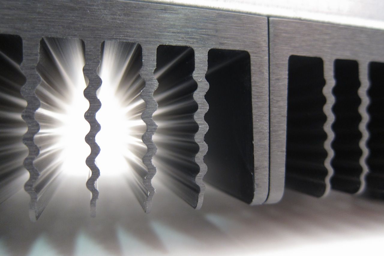
Just eyeballing the fins ins the picture that Jim posted, I would guesstimate the increase in fin area to be around 20 percent due to the waves. That would increase the effective fin height substantially for calculation of thermal resistance.
I suggest blacknoise a lot better ,I start using noctua in 2009...If it's not enough just add a Noctua fan, they are silent, particular off running a volt or two low.
Just eyeballing the fins ins the picture that Jim posted, I would guesstimate the increase in fin area to be around 20 percent due to the waves. That would increase the effective fin height substantially for calculation of thermal resistance.
Clever observation. Looks like you've got great gut feel Ben:
https://www.coolingzone.com/uploads/pdf-article/Heat%20Sinks%20and%20Heat%20Exchanger%20Fin%20Optimization.pdf
Very interesting. That probably explains why the simulation I used does not predict the performance of the wavy heatsink.
Looking at the photo in post #803, and assuming that the distance top-to-bottom is 40mm, I estimate the fin spacing to be closer to 10.5mm. Is the fin spacing really only 6mm as claimed in 40mm Heatsink Information – diyAudio Store
Looking at the photo in post #803, and assuming that the distance top-to-bottom is 40mm, I estimate the fin spacing to be closer to 10.5mm. Is the fin spacing really only 6mm as claimed in 40mm Heatsink Information – diyAudio Store
Last edited:
I worked though the surface area calculation in the paper and estimate only about 10.5% increase due to the sinusoidal waves in the fins.
I am still look for ΔC/W measurements from an actual build using those heatsinks.
I am still look for ΔC/W measurements from an actual build using those heatsinks.
I am looking to mount the top and bottom panels and the holes in the rails appear to be threaded? Am I still supposed to use the sheet metal screws? I tried to put one in and it knocked the threaded collar out.
Yes, I have examined all of the chassis and heatsink info at the diyAudio Store. Here is what I am looking for from the heatsink:
According to the information for the 210mm x 40mm x 400mm heatsink, the thermal resistance is 0.14C/W. That would imply a temperature rise of 0.14C/W*150W=21C which would be just fine.
- 2 FETs large footprint FETs per heatsink.
- IXYS SOT-227 approx 1.5 sq-in footprint
- Tokin 2SK182ES approx 2 sq-in footprint
- Each FET dissipating approx 75 Watts.
- Want temperature rise for the heatsink not to exceed 30C
However, the fin height of approx 31mm appears to be too short with the overall geometry of the heatsink to actually provide the 0.14C/W thermal resistance figure.
Can anyone verify that 0.14C/W number? Ie, compute C/W from the 2*Vrail*Ibias/(T_hsink-T_ambient) of an actual build.
Here is the original thermal dissipation documentation from the department of engineering at the university of Bologna, which is the source of the published figures. You are welcome to have it translated.
I am looking to mount the top and bottom panels and the holes in the rails appear to be threaded? Am I still supposed to use the sheet metal screws? I tried to put one in and it knocked the threaded collar out.
It may be that you were supplied the wrong (old style) bag of screws, which would have included self tapping screws, instead of the new nuts. The engineer is being consulted to debug this and we'll get back to you directly by email with a resolution as soon as we have an answer.
Here is the original thermal dissipation documentation from the department of engineering at the university of Bologna, which is the source of the published figures. You are welcome to have it translated.
Thanks for that intel.
Figure 52 is very handy with its indication of internal chassis temperatures. Looks like it was a relatively warm day in Bologna. Zero watts appears to land at somewhere between 27 - 32 °C depending on which graph you refer to.
I was hoping to spot reference to the ambient temperature but (if it's there) my Italian isn't good enough to pick the text to chuck into Google translate..
- Home
- The diyAudio Store
- Chassis Discussion