@Mark Johnson:
Thank you for the clarification on “PE.” The term, protective earth,” is much better than “ground” as this tends to get confused over and over with other grounds.
Thank you for the clarification on “PE.” The term, protective earth,” is much better than “ground” as this tends to get confused over and over with other grounds.

So the question are the if these interference are sufficiently attenuate in our installation. That means we should check what contaminated the electrical line, inside and outside of the house and try our best to attenuated these and after that, upgrade the line filter if this is not enough.
@Sidsmith: the Q on the table is how to check the level of EMI/RF contamination on safety/protective earth, to determine if the considerable expense of the choke on the PE is justified.
I ask because even after using a whole house surge protector and a rack unit style surge/ filter assembly, I still notice unexplained differences in sound quality. There are no RF “breakouts” or bursts of noise; instead the sound can go from good to “fuzzy” and without depth, or the reverse, in a matter of a minute, on occasion over a week with no correlation to time of day, lights or household equipment in or off, and voltage meter on rack unit showing unchanged voltage levels.
I ask because even after using a whole house surge protector and a rack unit style surge/ filter assembly, I still notice unexplained differences in sound quality. There are no RF “breakouts” or bursts of noise; instead the sound can go from good to “fuzzy” and without depth, or the reverse, in a matter of a minute, on occasion over a week with no correlation to time of day, lights or household equipment in or off, and voltage meter on rack unit showing unchanged voltage levels.
Could also be DC on the power lines. Even very small (order 1 Volt) DC offsets supposedly can wreak havoc on transformers, especially toroidal ones. There are filters/conditioners for that as well. But the first step is to measure. Don't just throw money and parts at the problem. Somebody somewhere on the web mentioned that you could get the power company to set up monitoring for the line voltage conditions at your house. I'm not sure which part of Earth this was true for, though. But it might not hurt to ask.
Found it, or a similar post: https://www.eevblog.com/forum/testgear/some-questions-about-power-analyzers/msg3558913/#msg3558913
Found it, or a similar post: https://www.eevblog.com/forum/testgear/some-questions-about-power-analyzers/msg3558913/#msg3558913
Last edited:
Folks, we're veering further and further away from discussing the chassis. If you wish to continue discussing various power line conditions, their effects, and possible ways to alleviate / mitigate those conditions or effects, let's use another thread, please.
Right, back on topic: Really happy with my 2U Galaxy enclosure 'without heatsinks'. The pair of Zenductor 2s run pretty stable at about 20W dissipation each, judging by the bias readout. I see about +/- 5% variation day to day and over extended running periods, i.e. 1.15 to 1.27 V measured over the inductor. 20W seems to be an ok amount of heat to run through one of the 280mm by 80mm side panels, with the more corrugated side facing out, if you want to stay below 60°C/140°F.
Thermal resistance works out to about (55°C - 25°C)/20W = 1.5 K/W, give or take.

The 3mm aluminum front and back panels work well for drilling and filing, 3mm apparently being a good compromise providing sufficient stiffness to prevent bending while working on it, and still being thin enough to make filing not too tedious. Nevertheless, it would be interesting to know whether @Gianluca or others have tried thinner, for example 2mm panels; drilling and filing would be easier/faster, but stiffness would be more than a factor three lower.
Regarding the available choices for heatsinks, has any thought been given to offering intermediate heatsinks, maybe using 10mm or 20mm tall vertical fins? There is a gap in the existing choices between the 0.3 to 0.6 K/W Deluxe/Dissipante chassis with 40mm tall fins, and the ~ 1.5 K/W no fins' Galaxy 2U chassis.
One could even replace the 10mm thick side panels with a 3mm base/7mm fin height heatsink, without changing the chassis overall dimensions. 10mm fins might not buy much in thermal performance over the existing side panels, so 20mm total thickness, with 17mm fins, might be better.
Thermal resistance works out to about (55°C - 25°C)/20W = 1.5 K/W, give or take.
The 3mm aluminum front and back panels work well for drilling and filing, 3mm apparently being a good compromise providing sufficient stiffness to prevent bending while working on it, and still being thin enough to make filing not too tedious. Nevertheless, it would be interesting to know whether @Gianluca or others have tried thinner, for example 2mm panels; drilling and filing would be easier/faster, but stiffness would be more than a factor three lower.
Regarding the available choices for heatsinks, has any thought been given to offering intermediate heatsinks, maybe using 10mm or 20mm tall vertical fins? There is a gap in the existing choices between the 0.3 to 0.6 K/W Deluxe/Dissipante chassis with 40mm tall fins, and the ~ 1.5 K/W no fins' Galaxy 2U chassis.
One could even replace the 10mm thick side panels with a 3mm base/7mm fin height heatsink, without changing the chassis overall dimensions. 10mm fins might not buy much in thermal performance over the existing side panels, so 20mm total thickness, with 17mm fins, might be better.
Last edited:
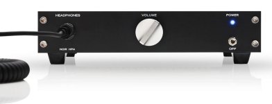
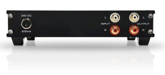
I've used 1.6mm epoxy fiberglass PCBs as front and back panels on the ModuShop Galaxy chassis. Mind you, these were for the smallest Galaxy of them all: 1U tall and 230mm wide. Those boards are sold in the diyAudio Store; check out the Noir headphone amplifier kit. At that small size, they seem plenty stiff enough, at least to me and to other builders of the Noir HPA. For bigger boards I theorize that one could solder brass tubing to the inside face of the front and rear panels, acting as stiffeners. But I haven't tried that myself, it's only a naive idea.
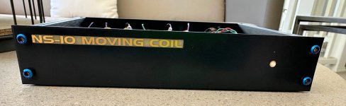
PCBs are advantageous because someone else (with super precise machine tools) does the drilling and the silkscreen printing, and you can use cool fonts and artwork if you like. You can also use the front copper and back copper to implement a Faraday Cage if that appeals to you; Noir does this. And finally, you have the option to remove the PCB solder mask and use HASL (silver color) or ENIG (actual gold metal) plated copper for text or artwork. An example of ENIG is shown below.
{look for the word FARADAY on the photo of the NS10 rear panel}
_
Attachments

Very interesting; thanks, Mark! HASL (hot air solder leveling) sounds attractive, but you probably want it with lead-free solder, if it's a surface that gets touched regularly. (The first HASL link I clicked on quoted a tin-lead mix for the coating.) With PC boards you could also integrate capacitive buttons into the front panel, and even make it full color!
Is just tinning an option as well, or does that not hold up well optically? Tin oxide is a conductor; we used that for some custom housing panels at work (and then covered them with Kapton, when we found out that our huge PC boards would bend just enough to allow some through hole mounted leads to touch the panel...), but those were not in plain view.
I do like the brushed aluminum look though.
Stiffness scales with the third power of both thickness and 1/length, so if 3mm is thick enough for a 300mm wide panel, then 2mm provides the same overall stiffness (i.e. when only supported at the ends) for a 200mm one. I'm just wondering whether 2mm would also be ok for a wider (300mm to 400mm) panel, since presumably you are going to support it somewhere locally when drilling or filing, and it would make manual work easier. If you get it machined professionally, then those considerations don't apply, and you might as well get 10mm.
Related: this heatsink calculator link seems pretty detailed, it computes the heat transfer coefficient to air based on the geometry and takes radiation into account. Also, somewhere early in the chassis announcement thread for the diyaudiostore there is a link to a useful note by @EUVL on chassis and heatsink considerations.
Using that calculator, a 270mm by 80mm heatsink with 7mm fins (10mm total sink thickness) will dissipate 18W for a Delta T of 35K (60°C max temp), whereas 17mm fins (20mm thickness) will allow 30W for the same Delta T, so a factor of 1.67 better.
Last edited:
- Home
- The diyAudio Store
- Chassis Discussion