CFH9
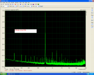
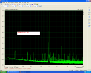
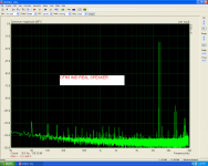
Testing the CFH9 using 7R,4R and 2R dummy load for comparison.
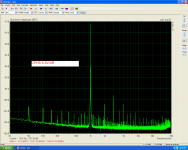
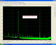
Testing CFH9 IMD using a 3way real speaker.
Testing the CFH9 using 7R,4R and 2R dummy load for comparison.
Testing CFH9 IMD using a 3way real speaker.
Attachments

Hello friends. That's better?
Using BC516-517 darlington in CapMult. Is a good idea?
Thiago
Apex showed that BC546/556 worked well - high gain is what we want I guess so Darlington may be better?
Testing the CFH9 using 7R,4R and 2R dummy load for comparison.
Testing CFH9 IMD using a 3way real speaker.
Thank you, Thimios for these measurements. To me, they appear excellent and I would say that if one listened to this amp the sound is very clear and transparent as 0.005% THD is indeed very low. I do not know how to interpret IMD figures are these good?
CFH9 on thimios recommandations
.......
.......
Attachments
Last edited:
No it's Shaan recommendation not mine!
But it's you that pointed it yo me..... 😉
Marc

I mentioned that something was not quite right with my plots earlier. I found even the dc levels unpredictable. Then when I tried a cap multiplier it looked much worse. So something was not right ! Well after a long search, I found the problem. Some intersecting lines joined up when it was not intended and so resulted in all the problems. So you will have to trash all the earlier plots I put up. I'm putting up some new ones that seem more reasonable ! Sorry for the bother.😱
I mentioned that something was not quite right with my plots earlier. I found even the dc levels unpredictable. Then when I tried a cap multiplier it looked much worse. So something was not right ! Well after a long search, I found the problem. Some intersecting lines joined up when it was not intended and so resulted in all the problems. So you will have to trash all the earlier plots I put up. I'm putting up some new ones that seem more reasonable ! Sorry for the bother.😱
Your efforts are appreciated here.
Post your attempts.
I accept criticism.
Thiago
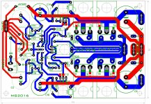
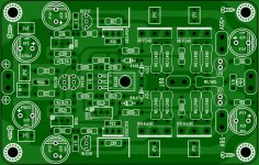
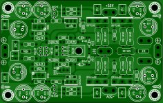
First and foremost, your layout looks great to me. I love the symmetry and the rounded traces - what layout software are you using?
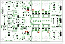
Looking at the silkscreen, are the two ecaps on the left 6.3V ?
Why is are the two 47R resistors the only ones with tolerance markings (1%)?
Please mark the boards with the design name and (my pet peeve) the revision.
Thx,
Ben Franklin
Hi thiago!
Great going!
The cutoff frequency of the RC network at the bases of the darlingtons is 0.7Hz. For any frequency higher than this present in the input signal the darlington's output impedance will be too high for powering the VAS and input. That is, the VAS and input will start to electrically "see" the darlington transistors in the rails, when they absolutely should not. Adding a 100uF from the darlingtons' emitters to ground will make it invisible to the stages.
A 10R 1/4 watt resistor between the power rails and the darlingtons' collectors will help remove the sudden load on the transistors during charging of the emitter to ground 100uF capacitors at power-on.
...Looking at the silkscreen, are the two ecaps on the left 6.3V ?
Yes. They see less than 2V at any signal level so 6.3V is more than enough!
Why is are the two 47R resistors the only ones with tolerance markings (1%)?
Because the amp's gain will be different in +ve slope and -ve slope resulting in increased even harmonic distortion if their values are not closely matched.
0.1% is more welcome!
CFH9
Well, a large heatsink is needed because VAS current vary from about 150mA when start to 220mA WHEN HEATSINK IS WARM ENOUGH.
Another solution will be mounting the VAS trans.on a separate heatsink
Well, a large heatsink is needed because VAS current vary from about 150mA when start to 220mA WHEN HEATSINK IS WARM ENOUGH.
Another solution will be mounting the VAS trans.on a separate heatsink
Hi Shaan, thanks for the tips.
I think this is the idea?
Yes. Nicely done!
One little thing, the 100K trimmers can be 20K for best compromise between control and range.
Well, a large heatsink is needed because VAS current vary from about 150mA when start to 220mA WHEN HEATSINK IS WARM ENOUGH.
Another solution will be mounting the VAS trans.on a separate heatsink
220mA VAS?


Did you mean 15-22mA?
220mA VAS?
Did you mean 15-22mA?
220 mA should be the total bias or the idle current.
To use a separate heatsink for the VAS transistor is not a good idea.
That is my opinion.
The VAS transistor has to monitor the same heatsink where the power devices mounted. My plan to mount on the top of the power mosfet or transistor like AKSA.. Maybe. Not sure🙂
220mA VAS?
Did you mean 15-22mA?
Yes, that would be smokin' hot. We would not need OPS if VAS could do that 🙂
Beautiful layout.
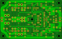
I don't see how the signal Gnd is tied to the Power Gnd ? Maybe I checked too quickly.
BR,
Eric
I can't see the voltage reference connection either.Thanks Hugh, it's always nice to know you like something I did.
Hi Eric, look again, two ground connections or a jumper can be made. thank you
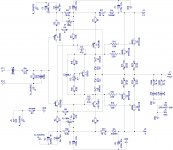
Here are the corrected curves . Schematic used from post 884 ( CHF-V4).
Red curve - PSRR +ve rail with Cap Mx BC546B/56K/220uF
Blue curve -PSRR -ve rail with Cap Mx BC 556B/56K/220uF
Black with RC filter 10 ohm / 220uF
Dashed black RC with 10 ohm/ 2,200uF
Green with RC filter 10 ohm / 220uF
Dashed green RC with 10 ohm / 2,200uF
I get the following from simulation with parts as shown on the schematic in post 884
VAS about 3.15 mA ( output set at 100mA )
Input stage about 1.3 mA. Both transistors don't have identical current.
Output clipping at about 35 V pk into 8 ohms with a +/- 42 volts split supply .
Gain = 26.1 dB ( = x 20.2)
Attachments

- Home
- Amplifiers
- Solid State
- CFH7 Amp