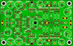
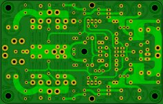
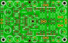
First and foremost, your layout looks great to me. I love the symmetry and the rounded traces - what layout software are you using?
Looking at the silkscreen, are the two ecaps on the left 6.3V ?
Why is are the two 47R resistors the only ones with tolerance markings (1%)?
Please mark the boards with the design name and (my pet peeve) the revision.
Thx,
Ben Franklin
The rounded traces are a positive as is the symmetry. There are a few places where there are some sharp edges - where the supply rails are narrowed to run under small plastic decoupling capacitors.
It should not be too much trouble to smooth these out. When there are smooth traces this helps to avoid any hf leakage into the ether - this is possible from sharp edges acting as an aerial to transmit.
The tolerance of 1 % for the 47R 's is specified because there are two negative feedback decoupling paths which seems to be an unshakeable article of faith with the design. Accordingly the nfb summing point of the two halves of the is removed to the region of input star earth through separate traces.
I dislike this and the job can be done differently as I described in my last post. In this I also raised the issue of electromagnetic radiation and making the input section more compact - there has been an improvement on this board however it could be taken a step further.
It is probably heresy to suggest SMD at this stage however it may have a place for input stages as a form of hybrid - there have been some better SMD components coming on the market
For the meantime, to reduce the physical size of the input and nfb decoupling capacitors there are other options than those rigidly adhered to. Firstly the feedback network 1k and 47R is very low and the increasing these values to 2k2 and 100R is still quite low permitting the nfb decoupling capacitor values to be reduced by a half. I would consider low impedance types in the smallest package I could find - albeit these would have to be ordered from a warehouse supplier.
The board caters for a larger diameter component which puts the prospective builder in a bind - having holes for multiple lead spacing would allow more flexibility permitting a more compact 2200uF unit. With the change in nfb resistor values the electrolytic caps could range from 470-1000 uF.
I note a reduction of the output stage stopper resistors to 100R down from 220R. With paired devices in each output half 100R may not be enough. A prototype should provide the answer.
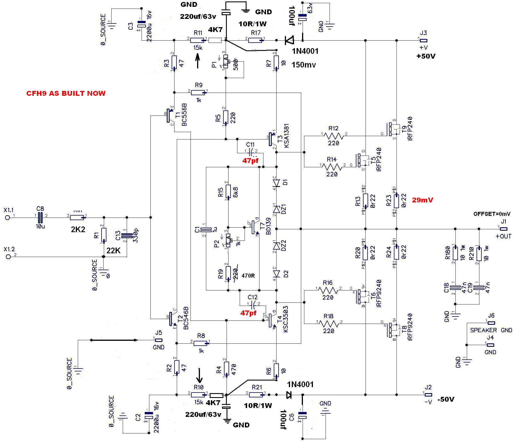
Sorry guys,please read 150mV up to 220mV on 10R=15 up to 22mA.Well, a large heatsink is needed because VAS current vary from about 150mA when start to 220mA WHEN HEATSINK IS WARM ENOUGH.
Another solution will be mounting the VAS trans.on a separate heatsink
Sorry.😡
I accept criticism.
Thiago
Please, Please post the circuit diagram also along with the PCB layouts
as Idefixes does ! Please !
Here are the corrected curves . Schematic used from post 884 ( CHF-V4).
Ashok, I am not sure I understand how your simulation is done, can you please explain, where is the signal injected in to and what is the amplitude used in your simulations?
One thing I am wondering is how the different filtering techniques will work if we modulate rails voltage with a signal of 1 or 2 Volts in order to mimic a rails voltage sagging under heavy load, all dependent on how well dimensioned the PSU is.
The reason for this is, I suspect the cap multiplier will fail badly if it isn't fed with a steady voltage, because if the output stage rails voltage sag more than 0,7 Volt, the transistor base capacitors will discharge through the base-emitter and base-collector diodes, and all the advantages with a cap multiplier are gone.
One solution is to have a series diode before the collector and a big electrolyte to the diode-collector node so the cap multiplier doesn't hike with the rails voltage at high load, or alternatively think of a different scheme and reevaluate whether the cap multiplier should be used at all.TOP
Last edited:
most Builders don't recognise this.I suspect the cap multiplier will fail badly if it isn't fed with a steady voltage, because if the output stage rails voltage sag more than 0,7 Volt, the transistor base capacitors will discharge through the base-emitter and base-collector diodes, and all the advantages with a cap multiplier are gone.
It's why we add in the lower resistor in parallel to the base to Zero volts capacitor.
You adjust the upper and lower resistor to give an output that is a fixed percentage of the nearly constant input voltage.
the output "tracks" the input. The output does NOT rely on a fixed input voltage.
You don't want the regulation to drop out when there is a severe sag of the input voltage.
Hello guys.
Is this flat earth welcome here?
The network feedback has been changed to 2k2-100R-1000uF.
RC before CapMult.
Thiago
Hi Thiago,
Very nice. Can you please post Schematic that goes with this so we can follow and help double check?
Have you simulated it to make sure it still works now that cap Mx is in place? Wow, Hfe of that Darlington is 30,000 vs typical 400-500 of BC546/556.
Also, please add board name, designer, layout, version number etc. info. I suggest calling this CFH9Cx.
Thanks,
X
Last edited:
Ashok, I am not sure I understand how your simulation is done, can you please explain, where is the signal injected in to and what is the amplitude used in your simulations?
One thing I am wondering is how the different filtering techniques will work if we modulate rails voltage with a signal of 1 or 2 Volts in order to mimic a rails voltage sagging under heavy load, all dependent on how well dimensioned the PSU is.
The reason for this is, I suspect the cap multiplier will fail badly if it isn't fed with a steady voltage, because if the output stage rails voltage sag more than 0,7 Volt, the transistor base capacitors will discharge through the base-emitter and base-collector diodes, and all the advantages with a cap multiplier are gone.
One solution is to have a series diode before the collector and a big electrolyte to the diode-collector node so the cap multiplier doesn't hike with the rails voltage at high load, or alternatively think of a different scheme and reevaluate whether the cap multiplier should be used at all.TOP
Yes most filters ,RC or cap multipliers, use a diode to the supply rail to prevent the supply to the input stage ( and cap multiplier!) from dropping due to supply sag on loud transients. That works very well. For sustained supply voltage drop ,the cap multiplier voltage will also drop but that isn't a problem.
To simulate the PSRR you must set the input signal to zero, add an ac signal in series with the supply rail voltage you are checking. Set this ac generator to be 1 volt ( 0 dBV). Then run the frequency sweep and you will see how much signal is visible at the output. Then remove this ac signal generator from the positive rail and repeat for the negative rail. The plot in dB gives you a direct reading for the PSRR since we set the ac signal at 0dBV ( 1 volt).
The simple cap multiplier doesn't regulate voltage ( not required). It just reduces supply borne signals which are mostly power supply ripple and harmonics. You need to keep the VCE of the cap multiplier sufficient for the transistor to be active. I usually keep it at 1.5 volts. So you loose that much margin for clipping. But the loss of power ( reduced output swing before clipping ) doesn't matter at all. You will not hear it at all.
Remember that if you want a regulated supply at the input stage you will loose more supply voltage to the input and that reduces the available output voltage even more. In that case they generally use a separate higher supply for the input stage. That's more expensive . However some circuits are very sensitive to the supply voltage and the output offset could shift too much or the dc bias might shift too much if the supply falls. In this case you will be forced to use a separate regulated supply rail for the input stage. Pick the type of supply that suits the circuit you are using. Selection is always a compromise which works for you.
With a decent transformer and sufficient supply caps ( fairly stiff supply rail) I'd just stick to the simplest desired solution. Most toroid transformers I see here have about 4 or 5% regulation at full load. EI types will be poorer , maybe 10%. With larger rated (VA) transformers the rails will be stiffer !
Last edited:

Thimios,
Rather than adding the 4.7k resistor to the 15k, could we not simply change 15k for 20k resistor? What impact did this have on the bias adjustment, did you have to readjust and was the current setup adequate for getting the full range of bias adjustment?
Is your recommendation for a new layout to replace the 15k resistors with two pots to effect both VAS adjustment and DC offset simultaneously?
Yes you can use 20K.
No other changes required
The offset control is very bad in this position . New schematic using two trimmer will be ok.
No other changes required
The offset control is very bad in this position . New schematic using two trimmer will be ok.
Hello guys.
Is this flat earth welcome here?
The network feedback has been changed to 2k2-100R-1000uF.
RC before CapMult.
Thiago
Capacitance multipliers are suitable for amplifiers that draw a substantially constant current. The earliest use I am aware of was in Linsley-Hood's Simple Class A amplifier of 1969.
The first condition is not true if the supply to the multiplier is shared by an output stage which performs a switching function as here and there is a problem of keeping output stage switching artifacts from contaminating the supplies to the first and second stages.
One option to deal with this would be to power the first two stages from a separately rectified supply - using pretty large capacitors.
I perceive there would be some feedback going on from the first two stages particularly the second which runs a relatively heavy current - this due to push pull action feeding back to the emitters of the capacitance multiplier transistors.
This prompts the "heretical" thought of using series regulators instead
Hi Thiago,
Very nice. Can you please post Schematic that goes with this so we can follow and help double check?
Have you simulated it to make sure it still works now that cap Mx is in place? Wow, Hfe of that Darlington is 30,000 vs typical 400-500 of BC546/556.
Also, please add board name, designer, layout, version number etc. info. I suggest calling this CFH9Cx.
Thanks,
X
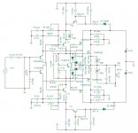
Schematic
Attachments
Amazing Work
Thiago,
Just to let you know that your pcb board is amazing as well as your schematics... Really nice work (almost a piece of art)
Will you make them available ? sell them ?
All the best
Christoph
Thiago,
Just to let you know that your pcb board is amazing as well as your schematics... Really nice work (almost a piece of art)
Will you make them available ? sell them ?
All the best
Christoph
Just off the cuff remarks.
1.Why have you increased the source resistors to 0.47 ohms ? 0.22 would have been fine .
2.Since the input transistors are selected to match Hfe the bleeder current in R2 the input resistor would be very low. So offset would be low and in any case you have an offset correction pot. You could raise the value of R2 to 47K ohms. You can reduce the input capacitor to 1uF. You get a -3dB point at 4 Hz which is good enough. Will also be useful if you use this with a valve preamp.
3.No inductance in the output to the speaker? You checked the square wave stability ?
4. The collector base resistors for the cap multipliers at 4.7K ( R25 and R28 ) appear too small. They should drop sufficient voltage so that the transistor is not starved for Vce voltage to keep it reasonably in the active region.
5.In the capacitance multiplier you don't need two resistors to the supply. As it is, it will not do very much. You can remove R23 and R26. C15 and C19 are too small. 22uF is not enough. At least make it 470uF. Where is the series diode ( 1N4007 ?) with R24 and R27 to the supply rails to isolate the input stage supply if the V supply drops significantly during a transient.
6. As it is You will need capacitors from the junction of R25/R23 and R26/R28 to ground for R23/R26 to be of any use . Looks like you are trying to pre-filter the supply rail twice, but that requires the cap I mentioned. Don't forget the diodes. I'm not so sure how useful they are in practice. I've made circuits with and without the diodes and don't really recollect any issues without them !
I'll have a closer look in a while.Maybe I'm missing something. I'm off for a dinner appointment !
PS: Did you actually work out the resistor values or just threw them in there ? For example I tried to simulate it but it would not even bias up the output stage. Looks like the input stage current is too low. You used 47K resistors for R9/R10. Earlier it was 15 K. I used 22K and the stage can bias the output.
OK ,I have to run or I'll be late!
Last edited:
Hi.
1- 2x0.47 R = 0.22R
2- I will increase.
3- PEECEEBEE worked well without inductor.
4- What value will you have?
5-R23-R26 Shaan said to keep. C15-C19 I will increase.
I am a bit confused with different opinions here. Which way to go?
1- 2x0.47 R = 0.22R
2- I will increase.
3- PEECEEBEE worked well without inductor.
4- What value will you have?
5-R23-R26 Shaan said to keep. C15-C19 I will increase.
I am a bit confused with different opinions here. Which way to go?
Nothing to get confused here. Read the reasons and you'll understand.
The two 0.47 resistors are not in parallel. They are on different transistors. Not equivalent of being in parallel.
You must check the square wave response with a capacitive load to determine if the inductor is required. On some speakers this may not be an issue.
I had used 47K in my simulation for the collector base resistor. It has very little base current.
R23 and R26 is not required here. Keep R24 and R27. I'll check it later. You need a capacitor directly from collector to ground. Now I really have to run. Bye.
Modified Layout
Sorry if I forgot to mention a few collaborate on PCB.
Thiago
Sorry if I forgot to mention a few collaborate on PCB.
Thiago
Attachments
Last edited:
- Home
- Amplifiers
- Solid State
- CFH7 Amp