xrk971: Your C2 and C3 2200uF /16V electrolytic caps are from Chong ?
The input cap is from Panasonic ( 10 uF polypropylene ) ?
Thanks.
The input cap is from Panasonic ( 10 uF polypropylene ) ?
Thanks.
xrk971: Your C2 and C3 2200uF /16V electrolytic caps are from Chong ?
The input cap is from Panasonic ( 10 uF polypropylene ) ?
Thanks.
Just cheap 2200uF 25v caps bag of 50 for $4. They are labeled Cheong? The input is 2.2uF 250v film cap from CBB bypassed with 10uF 50v ceramic.
Just cheap 2200uF 25v caps bag of 50 for $4. They are labeled Cheong? The input is 2.2uF 250v film cap from CBB bypassed with 10uF 50v ceramic.
Sorry, looking at photo it says ChongX VEHT 2200uF 25v. Anyhow still basic cheap caps by the bag full.
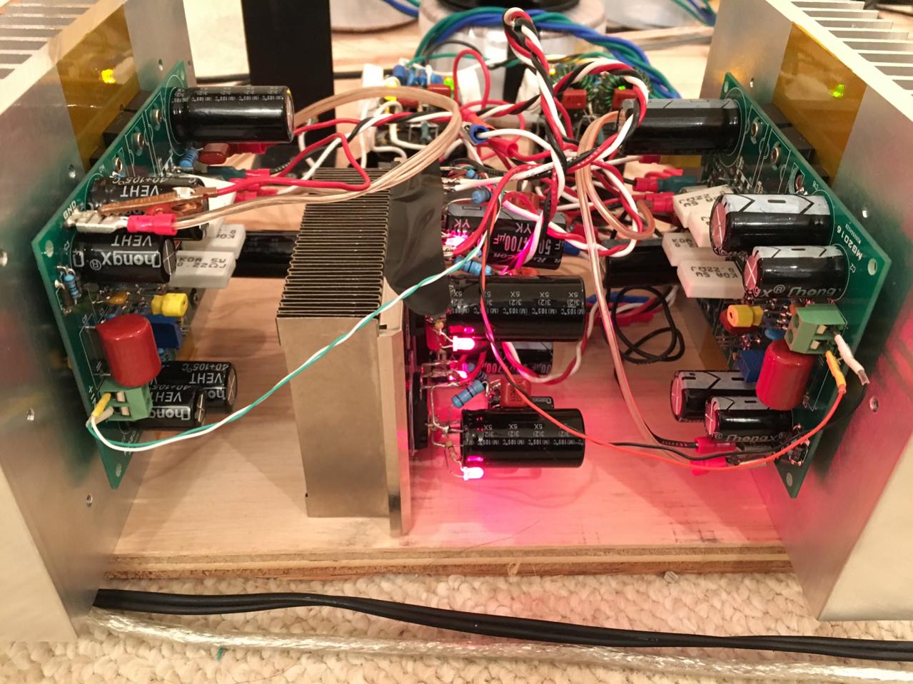
If the amp really sounds great , especially at LF and HF, it kind of proves that regular inexpensive components are often good enough.Here both these caps are at critical positions ! People often spend tons of money for boutique parts in these locations !🙂
Great job X!
It would be cool if somebody could show the spectrums 🙄

Thanks Valery! Sadly, I still don't have a sound card with low distortion capable of serving as a spectrum analyzer. I did manage to get an O-scope at least and the traces for the square waves look excellent so I suspect this amp is going to perform similar to the simulations which had THD at 0.005% at 1kHz and full power. Can't see the components though between H2, H3, H4, H5 etc...
I have a question for you - given that I am using a MOSFET to throttle the DC rails upstream of the amp, can that be used as a DC protect solid state relay and is there an easy and clever way to implement? I am thinking a couple small signal TO-220's to detect DC and maybe a low Rdson FET to clamp the IRFP240/9240 gate to ground? Almost like a 21st century protect but upstream.
Hmm, 0.005% simmed and suspecting amp performance similar to simmed?🙄
Dont see H2, H3, H4...on sim ? need to do careful sim, you could use LT spice with good models from Cordell and keantoken and others😉..
Hint, OS's models are quite close to reality, as he had said in some thread, if memory serves right.
Just a constructive suggestion🙂.
reg
Prasi
Dont see H2, H3, H4...on sim ? need to do careful sim, you could use LT spice with good models from Cordell and keantoken and others😉..
Hint, OS's models are quite close to reality, as he had said in some thread, if memory serves right.
Just a constructive suggestion🙂.
reg
Prasi
Last edited:
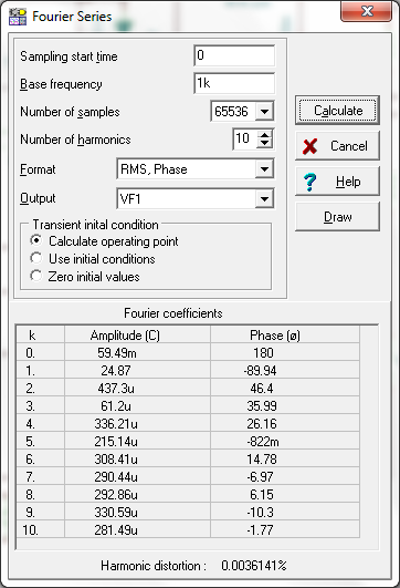
The sim had all the H2, H3, etc I am saying I don't have an analyzer to check in reality. I think models for KSA/KSC were from Cordell but model for IRFP's were straight from the included library for Tina. Sim actually says THD is 0.0036%, I said 0.005% for margin.
This is with 145mA bias current ea.
This is with 145mA bias current ea.
Attachments
Aha... now its clear!....The sim had all the H2, H3, etc I am saying I don't have an analyzer to check in reality. I think models for KSA/KSC were from Cordell but model for IRFP's were straight from the included library for Tina. Sim actually says THD is 0.0036%, I said 0.005% for margin.
This is with 145mA bias current ea.
if my read of designers' experiences here is accurate, sim and its margin dont agree with reality, unless its proven otherwise🙄.
anyway, nice work🙂!, sure will be watching progress of the thread.
Protection Circuit for CFHXX type Amps
I've been thinking about protection circuits for this type of amp. You could apply the classic VI limiters, but they sound awful with reactive loads and can actually cause destructive HF noise which kills tweeters. I wanted a softer clipping limiter and came up with a circuit that seems to work, but has a lot of parts. I guess they are cheap compared to repairing the amp or speakers, but somehow I'm not satisfied. So I am reaching out for ideas.
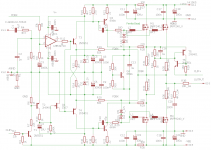
By the way, this amp is not CFH7, but my variant. It's similar, but I used a stabilized source for the input emitters and drew it differently, which just made more sense to me. The op amp on input is an experiment. I can bypass the op amp and compare performance with and without it. I see it as an error correction circuit, but don't want it to color the sound, so again, experiment. I'll probably try the National LME49710 here too, but it draws more current so I'll have to check the power budget. Anyway the op amp is unrelated to the clipping.
Take a look at the clipping limiter I put on this, circled. It seems more complex than I wanted, but I think it works. It's a soft limiter at about 10A, fast attack slow decay. I borrowed this from the Mission Cyrus 1 amp, but used the JFET because ... well, because there was no current source to choke. Looking for better ideas. This should be simpler. Thoughts?
I've been thinking about protection circuits for this type of amp. You could apply the classic VI limiters, but they sound awful with reactive loads and can actually cause destructive HF noise which kills tweeters. I wanted a softer clipping limiter and came up with a circuit that seems to work, but has a lot of parts. I guess they are cheap compared to repairing the amp or speakers, but somehow I'm not satisfied. So I am reaching out for ideas.
By the way, this amp is not CFH7, but my variant. It's similar, but I used a stabilized source for the input emitters and drew it differently, which just made more sense to me. The op amp on input is an experiment. I can bypass the op amp and compare performance with and without it. I see it as an error correction circuit, but don't want it to color the sound, so again, experiment. I'll probably try the National LME49710 here too, but it draws more current so I'll have to check the power budget. Anyway the op amp is unrelated to the clipping.
Take a look at the clipping limiter I put on this, circled. It seems more complex than I wanted, but I think it works. It's a soft limiter at about 10A, fast attack slow decay. I borrowed this from the Mission Cyrus 1 amp, but used the JFET because ... well, because there was no current source to choke. Looking for better ideas. This should be simpler. Thoughts?
Attachments

Last edited:
I've been thinking about protection circuits for this type of amp. You could apply the classic VI limiters, but they sound awful with reactive loads and can actually cause destructive HF noise which kills tweeters. I wanted a softer clipping limiter and came up with a circuit that seems to work, but has a lot of parts. I guess they are cheap compared to repairing the amp or speakers, but somehow I'm not satisfied. So I am reaching out for ideas.
By the way, this amp is not CFH7, but my variant. It's similar, but I used a stabilized source for the input emitters and drew it differently, which just made more sense to me. The op amp on input is an experiment. I can bypass the op amp and compare performance with and without it. I see it as an error correction circuit, but don't want it to color the sound, so again, experiment. I'll probably try the National LME49710 here too, but it draws more current so I'll have to check the power budget. Anyway the op amp is unrelated to the clipping.
Take a look at the clipping limiter I put on this, circled. It seems more complex than I wanted, but I think it works. It's a soft limiter at about 10A, fast attack slow decay. I borrowed this from the Mission Cyrus 1 amp, but used the JFET because ... well, because there was no current source to choke. Looking for better ideas. This should be simpler. Thoughts?
Thanks for sharing but I am not understanding how the protect works. It does not appear to control either outputs or the supplies to the outputs, so if there was a fault, the output could still swing full rail and not be stopped - I must be missing something here.
I read this statement by DPH today and it seems to make sense. I wonder if multi output pair class AB amps will probably sound better because of the dithering (averaging) that reduces crossover distortion.
* In fact, crossover distortion is actually somewhat minimized in a class-AB/B stage with multiple pairs as there is some dithering of the crossover region by each individual transistor. Minutia, though.
Each handover from one device to another produces discontinuities which show up as H5, H7, H9 and beyond. More pairs will increase transconductance, reducing compressive distortion, but many pairs will also produce wider discontinuities of crossover which create a bit more THD. Swings and roundabouts......
HD
HD
i could do the measurements but i haven't the pcb.Thanks Valery! Sadly, I still don't have a sound card with low distortion capable of serving as a spectrum analyzer. I did manage to get an O-scope at least and the traces for the square waves look excellent so I suspect this amp is going to perform similar to the simulations which had THD at 0.005% at 1kHz and full power. Can't see the components though between H2, H3, H4, H5 etc...
I have a question for you - given that I am using a MOSFET to throttle the DC rails upstream of the amp, can that be used as a DC protect solid state relay and is there an easy and clever way to implement? I am thinking a couple small signal TO-220's to detect DC and maybe a low Rdson FET to clamp the IRFP240/9240 gate to ground? Almost like a 21st century protect but upstream.
The two transistors attached to the output are a discrete Thyristor.Thanks for sharing but I am not understanding how the protect works. It does not appear to control either outputs or the supplies to the outputs, so if there was a fault, the output could still swing full rail and not be stopped - I must be missing something here.
When triggered these conduct (short) from top to bottom leads.
This pulls current from that input stage connection.
The Thyristor stays latched after triggering until the current through it falls below the turn off level.
The Cyrus version measures across both emitter/source resistors. This way the Thyristor can trigger on excessive shoot through current (input frequency too high) and/or on excessive output current (output load too low for the intended voltage). The sensitivities for these are different by a factor of ~2
AKSA +1
The "dithering" can also be described as smearing. In my opinion, this is a case of exchanging one type of distortion for another. You might reduce crossover distortion and discover a loss of presence, dynamics and/or detail. I don't know the measurement or spec that will expose these with any certainty. It would be in the ears of the listener. Good work, to all involved but especially to AndrewT for consistently putting up the road signs.
The "dithering" can also be described as smearing. In my opinion, this is a case of exchanging one type of distortion for another. You might reduce crossover distortion and discover a loss of presence, dynamics and/or detail. I don't know the measurement or spec that will expose these with any certainty. It would be in the ears of the listener. Good work, to all involved but especially to AndrewT for consistently putting up the road signs.
Last edited:
i could do the measurements but i haven't the pcb.
I would send you one but all boards have been spoken for in the GB. 🙁
Never mind my friend,may be another time.🙂I would send you one but all boards have been spoken for in the GB. 🙁
Thanks for sharing but I am not understanding how the protect works. It does not appear to control either outputs or the supplies to the outputs, so if there was a fault, the output could still swing full rail and not be stopped - I must be missing something here.
I was not clear. This is not a traditional protection circuit, it's more an automatic volume limiter. Other protection must deal with faults. I assume the amp is overdriven, or the speaker wires are shorted -- user error. Those are very common events, and I wanted a clean way to deal with them.
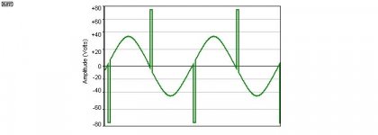
Why bother? We do know how to make VI limiters that clamp output stages. VI limiters work -- they do prevent fires, assuming the amp works enough to clamp. But they sound awful, because with reactive loads they false trigger, chop the output and then the reactive load dumps back into the amp, typically at zero crossings. So the amp is safe, but this back emf kills tweeters and sounds trashy. Phil Anderson and Rod Elliot explained the problem here:
VI Limiters in Amplifiers
In brief, the picture below tells the story, exaggerated. Ugly, no?
My old Mission Cyrus One Amp used this concept. So I wanted to apply it here. Mission used a clamp on the LTP current source to do it, but this current feedback amp has no such control point. So, I fell back to an old idea I used in a friend's guitar amp in 1978, which I remember very well because he raved about it - it let him just play, without diddling the volume control while performing.
So here I wanted to automatically turn down the volume for a period when overcurrent was detected. I don't want the VI limiter hash, but I do want to guard against the most common fault, which is user error. This automatic volume control circuit aims to do that, with a fast attack, slow decay. Overcurrent detection is sensed by the transistor pair on the output, which make a Schmitt trigger, or thyristor, depending on how you view it. The JFET is a sort of automatic volume control, clamping the input to ground when its gate is at zero volts.
This circuit only works on a functional amp, and there must be other protection in case of failures. I assume there is a separate loudspeaker protection circuit external to the amp, and power fuses and so on, although I like your Cap multiplier much better for that. Anyway this is pretty complex, and I was hoping to keep it simple to match the simplicity of the amp. I'm not satisfied with this.
I have done a trial layout though, it's buildable on a 3x4 board, free Eagle's limit. It might fit on a 2x4 board, if I leave out stuff and use more SMD bottom side. These are paper designs, not tested, subject to change, but I'll share the current state of the schematic and board below.
Attachments

Never mind my friend,may be another time.🙂
Just remembered I have a single board I can give you (order was for 15 so odd one left).
For folks in GB, I have managed to send 2 sets out over weekend and will send remaining 4 sets today. Some of you have very very long addresses. Like room x, in building y, on such and such street off another street z and halfway through the middle of district W in township T, country Xyz. 🙂
Last edited:
The two transistors attached to the output are a discrete Thyristor.
When triggered these conduct (short) from top to bottom leads.
This pulls current from that input stage connection.
The Thyristor stays latched after triggering until the current through it falls below the turn off level.
The Cyrus version measures across both emitter/source resistors. This way the Thyristor can trigger on excessive shoot through current (input frequency too high) and/or on excessive output current (output load too low for the intended voltage). The sensitivities for these are different by a factor of ~2
Thanks for explaining this so clearly. You nailed it.
I did not understand a couple of things though. By shoot through current, do you mean cross conduction? Possibly due to input frequency too high, or Vbias not tracking, or?? Always a concern. I show fixed bias, but probably need a pot for tweaking.
And, what do you mean by "sensitivities for these are different by a factor of ~2"? I figured the original Cyrus had about a 7A trip, this was upped to about 10.5A in my implementation. Those were trial values, because I want to test this to see if it either nuisance triggers because the limit is low, or fails to trigger on harmful overcurrent.
I'm still looking for a simpler way to do this.... The original CFH7 design had only 7 actives, and I hated to add 5 actives just for this AGC function. I'm still pondering this. My earlier version had an optocoupler for sensing and level translating the overload detect, which was simpler. I also considered using the protective zeners (by lowering their voltage) but that becomes VI limiting and it's imprecise.
I like the Cyrus thyristor design and I know it works well, so it's in for now. Still going back and forth.
- Home
- Amplifiers
- Solid State
- CFH7 Amp