Idefixes:
I ran some more sims for different capacitive loads and the Thiele network seems to work best over a broader range with 2uH and 10R, with 4.7R and 100nF Zobel (snubber). Looking forward to seeing the layout. Any sneek peeks at the general construct?
Thanks,
X
I ran some more sims for different capacitive loads and the Thiele network seems to work best over a broader range with 2uH and 10R, with 4.7R and 100nF Zobel (snubber). Looking forward to seeing the layout. Any sneek peeks at the general construct?
Thanks,
X
Hi X,
What is you final choice for out. I am on layout and with or whitout inductor it is not the same in terme of space.
Marc
What is you final choice for out. I am on layout and with or whitout inductor it is not the same in terme of space.
Marc
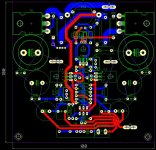
Let's leave the inductor - but I only need a 20mm x 20mm square above the resistor to have a vertical coil (axis up and down).
Here is an example of how to do it and not use too much space:
Here is an example of how to do it and not use too much space:
Hi Marc and X.
Ah, i see the Quasi is on live here, only for example, i know.
Because i know that your are a very good double sided pcb designer i am very
inquisitively to see a nice compact board in reality next time.
I have actually begin to learn in use Eagle Software- its a fun to learn.
Regards Bangla.
Ah, i see the Quasi is on live here, only for example, i know.
Because i know that your are a very good double sided pcb designer i am very
inquisitively to see a nice compact board in reality next time.
I have actually begin to learn in use Eagle Software- its a fun to learn.
Regards Bangla.
Hi Marc and X.
Ah, i see the Quasi is on live here, only for example, i know.
Because i know that your are a very good double sided pcb designer i am very
inquisitively to see a nice compact board in reality next time.
I have actually begin to learn in use Eagle Software- its a fun to learn.
Regards Bangla.
Not as conmpact as i would because of cap size and inductor place....
Marc
Hi Marc and X.
Ah, i see the Quasi is on live here, only for example, i know.
Because i know that your are a very good double sided pcb designer i am very
inquisitively to see a nice compact board in reality next time.
I have actually begin to learn in use Eagle Software- its a fun to learn.
Regards Bangla.
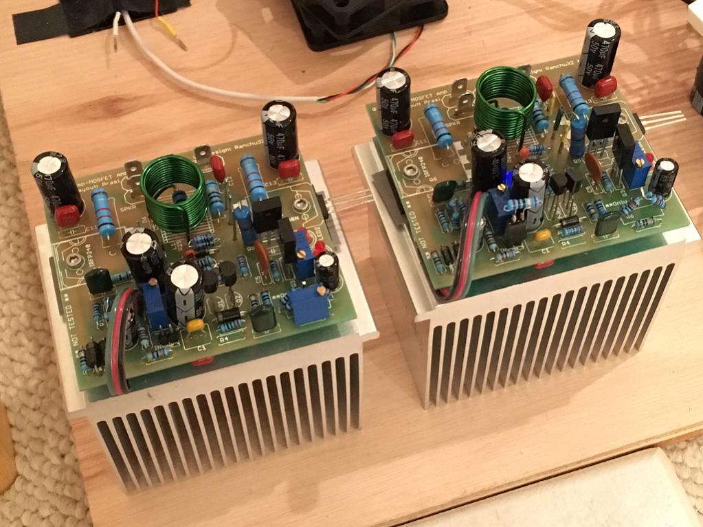
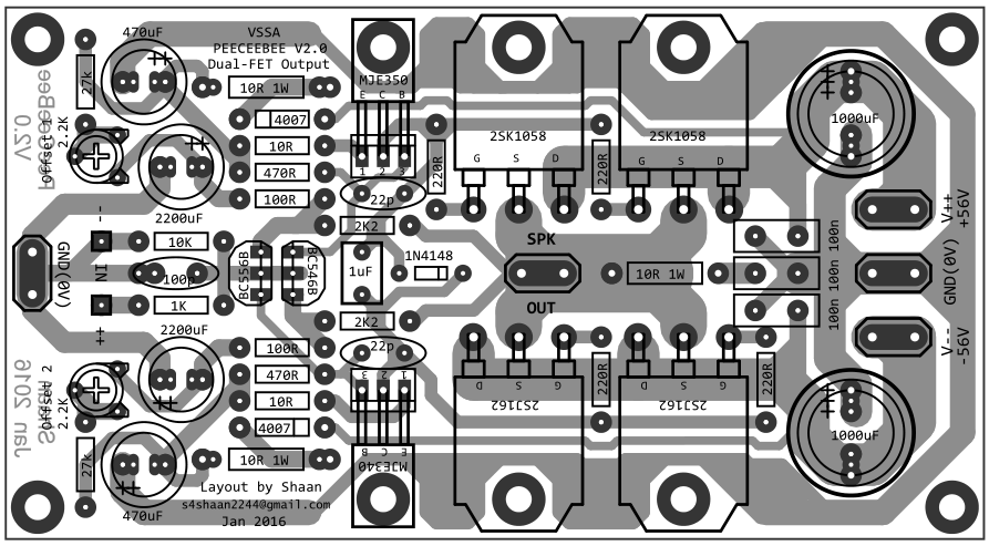
Yes, the Quasi was shown just as an example of how to squeeze on a vertical oriented inductor. Those $4 surplus Dell CPU heatsinks are working quite nicely and I think I will order more. Add a small 60mm fan and they can handle 75w to 100w dissipation easily. 25w without fan works.
Nicely done Idefixes!

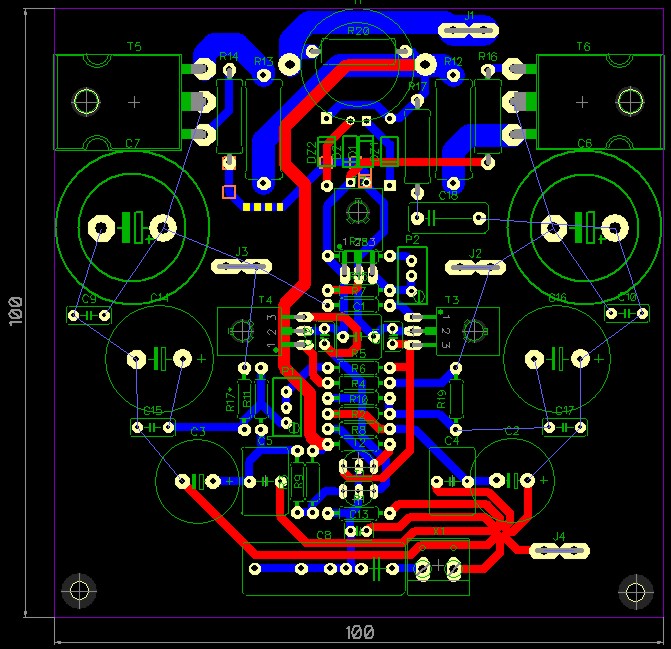
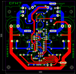
Edit: looking at it closer I really appreciate the elegance of the layout. I have never seen a design with all the resistors down the middle like that with transistors on the sides - almost reminds me of the decoration on 18th century soldier's uniforms.

Now the hard work of eyes manually following traces and comparing to schematic. Did you use software that shows routing errors as "air wires" left remaining? Or was this a manually done like with Sprint?
So far so good though.
Edit: looking at it closer I really appreciate the elegance of the layout. I have never seen a design with all the resistors down the middle like that with transistors on the sides - almost reminds me of the decoration on 18th century soldier's uniforms.
Now the hard work of eyes manually following traces and comparing to schematic. Did you use software that shows routing errors as "air wires" left remaining? Or was this a manually done like with Sprint?
So far so good though.
Last edited:

Now the hard work of eyes manually following traces and comparing to schematic. Did you use software that shows routing errors as "air wires" left remaining? Or was this a manually done like with Sprint?
So far so good though.
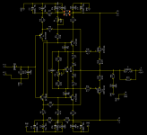
I use diptrace after using eagle for year....Diptrace as eagle provide correlation between schematic and layout so they shouldn't be mistake...check first schematic above and than layout.
Marc
Hi Idefixes,
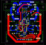
Everything looks good - there is one request and it was Egra who suggested that the front end ground get its own ground terminal and be separated from the power ground bus. Supposedly in the PeeCeeBee it helped to reduce noise induced into the front end. So the little trace connecting the large power ground to the star hub needs to be broken. Then add another ground spade terminal near the input stage star hub.
Thanks,
X
Hello xrk! 
Great to see you pursuing this topology.
Japan? Damn I wish I could find the original designer to convey my thanks.
You are right about the added bit of complexity in the powering scheme, but isolating the input/feedback ground right at the PSU ground has advantages regarding noise/hum level. It requires just one more wire so the real-world impact is relatively lower than what it looks like. That said, your final design might have better hum performance and not need the split.
All the bests and happy tweaking! 🙂 😉
Great to see you pursuing this topology.
Japan? Damn I wish I could find the original designer to convey my thanks.
Ok, I see a separate ground pin and circuit on the left side for the input stage. This will make the PSU the star ground hub then?
It makes the circuit a little more complicated to layout.
You are right about the added bit of complexity in the powering scheme, but isolating the input/feedback ground right at the PSU ground has advantages regarding noise/hum level. It requires just one more wire so the real-world impact is relatively lower than what it looks like. That said, your final design might have better hum performance and not need the split.
All the bests and happy tweaking! 🙂 😉
Hi Idefixes,
Everything looks good - there is one request and it was Egra who suggested that the front end ground get its own ground terminal and be separated from the power ground bus. Supposedly in the PeeCeeBee it helped to reduce noise induced into the front end. So the little trace connecting the large power ground to the star hub needs to be broken. Then add another ground spade terminal near the input stage star hub.
Thanks,
X
HI corresponding to your request without whole change....
Marc
Attachments
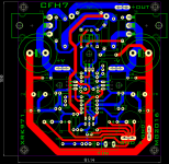
So, maybe we can make a bridgeable ground between the input stage and output stage but leave capability for two ground wires. And then up to the user to decide which grounding scheme is better?
Me too. Perhaps it was Sony San or Matsushita San himself? 🙂
Japan? Damn I wish I could find the original designer to convey my thanks
Me too. Perhaps it was Sony San or Matsushita San himself? 🙂
- Home
- Amplifiers
- Solid State
- CFH7 Amp