Hi Ashok! I agree. CCS will improve the precision of the feedback network at higher frequencies by an order of magnitude than that with a resistor. The PSRR will also be higher with CCS. It has an instant effect on the thermal stability, SN ratio, THD, etc. I tried CCS in PeeCeeBee (1LED+1Q, and 2Q). The difference was very small, but after 2-3 week of everyday listening the CCS version seemed a bit sterile. I know this is very subjective but I still prefer the single resistor version. Photographic analogy of my listening impressions I attached bottom.
Attachments

With source material like this, it won't matter what amp you play it in, guaranteed to be good! 🙂
So, in a way, I am glad I picked the simple resistor approach.
So, in a way, I am glad I picked the simple resistor approach.
For those who are interested in Canopus' layout (.LAY files):
HEED canopus, obelisk /HTA-30/ - Hobbielektronika.hu - online elektronikai magazin és fórum
HEED canopus, obelisk /HTA-30/ - Hobbielektronika.hu - online elektronikai magazin és fórum
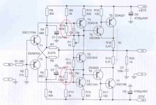
The publisher (The founder of HeedAudio) wrote what is the point of using those resistors between base and collector of VAS transistor: " Those are forming a negative voltage feedback network, which decreases the gain of VAS stage, but improves the linearity and transient behaviors of the amplifier." Since Canopus has 10dB feedback only this kind of local feedback of VAS will not decrease the closed loop gain significantly.
Attachments
The publisher (The founder of HeedAudio) wrote what is the point of using those resistors between base and collector of VAS transistor: ....................
Yes Egra, on looking at it closely those resistors would do that. Hugh has also explained it in a similar fashion and mentioned the 'audible improvement' on playing music. It's not easy to determine the improvement it makes audibly by a simple examination. Great implementation!
Thanks for posting the original publishers comment.
Egra, that's a great way of showing the difference, using a photograph ! Never thought of that before ! 
Measurable benefit using VAS loading resistor
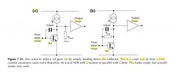
Hi XRK, Ashok! Douglas Self prefers the method used in Canopus over the resistor connected from collector to ground. Take a look at the first picture I attached. Ostripper (OS) takes a different opinion. He wrote:
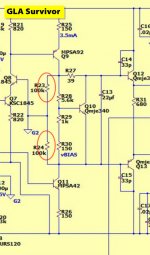
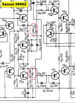
"Conclusion - loading sacrifices gain at lower frequencies for more gain at the higher ones. 1/5th the THD at 20K is the result. TMC does the same work in a typical "blameless" topology.This is also why you see the THD plots of most amps " reach skyward" at 25 to 30k - no extra gain above 20K ! this is why Sansui used the loading resistor."
"R25 and R26 load the VAS gives a monotonically decaying harmonic output."
http://www.diyaudio.com/forums/solid-state/243842-gla-good-little-amp-survivor-3.html#post3665643
I think it's worth to try this "mod" in CFH7 as well.
Hi XRK, Ashok! Douglas Self prefers the method used in Canopus over the resistor connected from collector to ground. Take a look at the first picture I attached. Ostripper (OS) takes a different opinion. He wrote:
"Conclusion - loading sacrifices gain at lower frequencies for more gain at the higher ones. 1/5th the THD at 20K is the result. TMC does the same work in a typical "blameless" topology.This is also why you see the THD plots of most amps " reach skyward" at 25 to 30k - no extra gain above 20K ! this is why Sansui used the loading resistor."
"R25 and R26 load the VAS gives a monotonically decaying harmonic output."
http://www.diyaudio.com/forums/solid-state/243842-gla-good-little-amp-survivor-3.html#post3665643
I think it's worth to try this "mod" in CFH7 as well.
Attachments
Last edited:
The publisher (The founder of HeedAudio) wrote what is the point of using those resistors between base and collector of VAS transistor: " Those are forming a negative voltage feedback network, which decreases the gain of VAS stage, but improves the linearity and transient behaviors of the amplifier." Since Canopus has 10dB feedback only this kind of local feedback of VAS will not decrease the closed loop gain significantly.
Egra can we sign those two 100K resistors as `Shade` resistors? 🙂
Best Regards !
Egra can we sign those two 100K resistors as `Shade` resistors? 🙂
Best Regards !
Yes, we can 🙂 What's your opinion on this "mod"?
Last edited:
Egra
It is obvious that those two res.+ that two 10p cond. forms simple & very effective local NFB network around to both VAS stages ,
result is little less gain from both VAS , but in the same result will be better VAS linearity ,which is one not so insignificant basic effect ,
all in all applied GNFB in that case need to be with less value to get desired CLG ,
exact measurements need to be done for sure , but as always relaxed & unbiased listening test will be the final judge .
edit ,2x100K is not one fixed universal value , another values can be implemented to , even with slightly different values for top and bottom PP-VAS .
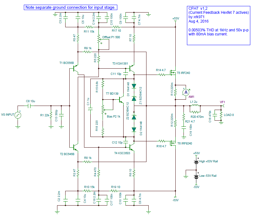
You lost me - I can understand the diagram with simple R from collector in parallel with compensation cap but don't see how that is implemented in following schematics. Could someone markup current CFH7 schema with proposed loading resistors? Maybe can be added via hard wire jumper after the fact as boards are now completed and awaiting shipment.
If this is the circuit you are looking at,
http://www.diyaudio.com/forums/attachments/solid-state/563197d1470315662-cfh7-amp-cfh7-sch-v1.2.png
Then the resistors will be across C11 and C12 . Start with something like 100K.
http://www.diyaudio.com/forums/attachments/solid-state/563197d1470315662-cfh7-amp-cfh7-sch-v1.2.png
Then the resistors will be across C11 and C12 . Start with something like 100K.
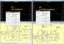
I ran a sim of what you suggested and the THD increased from 0.004% to 0.007% at 1khz. It wasn't better at 20kHz - even worse.
Could this have something to do with fact that MOSFET gates don't draw current in same way that BJT base does? Gate is infinite impedance to DC and presents a capacitive load to the VAS transistor.
Could this have something to do with fact that MOSFET gates don't draw current in same way that BJT base does? Gate is infinite impedance to DC and presents a capacitive load to the VAS transistor.
Yes the distortion figures could get worse due to the lowered open loop gain available. But from 0.004 to 0.007 I don't think it matters at all audibly.
Need to see the envelope of the harmonic spectrum. If the higher harmonics don't go up, it should not be a problem.
But as mentioned earlier by others and Hugh , you may not see anything significant in measurement, do a listening test ! That difference is not measurable , I guess maybe because we don't know what to measure !🙂
I can certainly try that once the boards come in and I build it. As it requires a simple parallel across a capacitor I can just leave the legs on cap long to solder a resistor onto.
Hello xrk971
greetings can CFH7 work in 4 ohms at 35 dc rails +/-
warm regards
Andrew
Yes, a single pair of IRFP240/9240 can handle 4ohm loads just fine at 35v rails.
- Home
- Amplifiers
- Solid State
- CFH7 Amp