HI corresponding to your request without whole change....
Marc
Oh that looks really nice - you are a true artist!
Thanks so much. The circuit looks good - does anyone else have any comments? We might be pretty close to issuing a Gerber.
Let me mull it over another day. 🙂
Add HBRR between the Signal Return and the Speaker Return/Power Ground
For added safety you can add inverse parallel power diodes (1n400x or 1n540x) across HBRR.
In a true mono-block HBRR can be 0r0 copper link
In a multichannel build (including dual mono) HBRR can be between 1r0 and 100r, most choose around 10r.
For added safety you can add inverse parallel power diodes (1n400x or 1n540x) across HBRR.
In a true mono-block HBRR can be 0r0 copper link
In a multichannel build (including dual mono) HBRR can be between 1r0 and 100r, most choose around 10r.
Last edited:
Add HBRR between the Signal Return and the Speaker Return/Power Ground
For added safety you can add inverse parallel power diodes (1n400x or 1n540x) across HBRR.
In a true mono-block HBRR can be 0r0 copper link
In a multichannel build (including dual mono) HBRR can be between 1r0 and 100r, most choose around 10r.
So Andrew?
Marc
Attachments

Hi Idefixes,
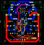
Thanks for the layout - after studying it now for some time I can't find anything else to comment on. It looks great. Can you please generate a Gerber file zip package? I am not sure if you are doing this - but can you please put actual values on the top silk screen? For the output network it should be labeled 2uH coil and R21 = 10R and R18 should be 4.7R. C18 should be 100nF.
Thanks,
X
Hi Idefixes,
Thanks for the layout - after studying it now for some time I can't find anything else to comment on. It looks great. Can you please generate a Gerber file zip package? I am not sure if you are doing this - but can you please put actual values on the top silk screen? For the output network it should be labeled 2uH coil and R21 = 10R and R18 should be 4.7R. C18 should be 100nF.
Thanks,
X
I will see for value, but i don't like to put them on silk. It provide to much information on pcb. For me Parts def. is more important as value can be changed and than provide mistaken info.
I can generate gerber files. I do this way for board house for me.
Marc
I will see for value, but i don't like to put them on silk. It provide to much information on pcb. For me Parts def. is more important as value can be changed and than provide mistaken info.
I can generate gerber files. I do this way for board house for me.
Marc
I'm good with leaving values off as well. Thanks!
Hi XRK, very nice hexfet VSSA amp. I'll make single side diy friendly layout once I am free.
@ Idefixes, nice layout and thanks for gerbers.
Regards,
Sonal Kunal
@ Idefixes, nice layout and thanks for gerbers.
Regards,
Sonal Kunal
Thanks Sonal! Looking forward to it. 🙂
@Idefixes: Thank you for the layout design and Gerbers! I just uploaded to PCBway.com...
@Idefixes: Thank you for the layout design and Gerbers! I just uploaded to PCBway.com...
Thanks Sonal! Looking forward to it. 🙂
@Idefixes: Thank you for the layout design and Gerbers! I just uploaded to PCBway.com...
Real life is near...
Marc
The raw boards are being cut at present. Should be done in a few days then another week for shipping. So yes, reality is near. 🙂
The moment of truth will be upon me after stuffing and soldering and connected to PSU.
The moment of truth will be upon me after stuffing and soldering and connected to PSU.
The circuit from post 44 posted by 'egra' is interesting with a CFP output stage.
Would be interesting to see how it compares with a P3A ( audibly!) and the current circuit that's being implemented by many.
Would be interesting to see how it compares with a P3A ( audibly!) and the current circuit that's being implemented by many.
The circuit from post 44 posted by 'egra' is interesting with a CFP output stage.
Would be interesting to see how it compares with a P3A ( audibly!) and the current circuit that's being implemented by many.
I wonder if Egra has Gerber files of his "Canopus" amp that can be shared?
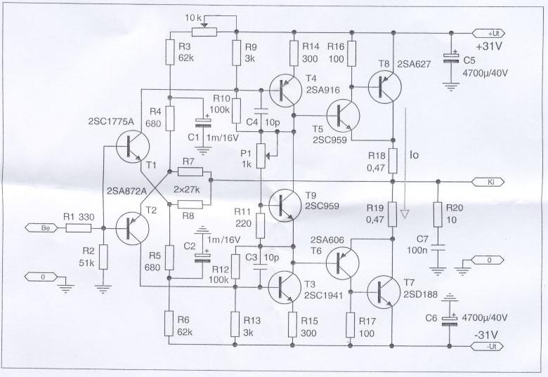
It does indeed look interesting as a 9 actives BJT implementation that is very elegant.
The circuit from post 44 posted by 'egra' is interesting with a CFP output stage.
Would be interesting to see how it compares with a P3A ( audibly!) and the current circuit that's being implemented by many.
Hi Ashok! I didn't make a direct comparison between two, but from memory I would say that Canopus had a bit "rounded" highs and tiny bit deeper and warmer low end than P3A. Its sonical character is very smooth and dymanic, no listening fatigue. After several month of listening Canopus swept out my Mission Cyrus III+PSX-R, wich says a lot. 🙄 This is strange because Cyrus III has similar but more advanced topology with CCS in first stage, diamond buffer, 3EF output.
I wonder if Egra has Gerber files of his "Canopus" amp that can be shared?
It does indeed look interesting as a 9 actives BJT implementation that is very elegant.
Unfortunately not. This was my first PCB design using software (Protel 98). But it is pretty simple to redesign it using Sprint layout.
Hi Egra,
I found several times that introducing a ccs where there is a resistor makes measured performance much better but isn't as good audibly as a plain resistor .
Even with 'some' tubes circuits I preferred the sound with resistors rather than a CCS loaded one. Do you have an explanation ? Could it be that though distortion is lowered at LF it starts rising later on ? Is a tilt in the envelope of the harmonics that affects the perceived sound?
It's unfortunate that I can't do anything thing now as I'm in the middle of shifting home. I will build your circuit and the P3A and compare them. Also the Quasi of course. All with on board power supply...mono blocks. Will take at least 7 weeks before I can start work again.🙁
I still have not figured out why there is local feedback around T4,T3 , using R10,R12. Is it essential. I've done that in a similar circuit without CFP and it worked fine..
Based on my experiments I suspect C1 and C2 can significantly affect the perceived quality of the HF. Some brands being better than others. P1 should have been in the place of R11. That makes it fail safe. If the slider lifts off the bias voltage drops. The other way around the bias will shoot up due to a failure of the slider.
As always refinements are possible easily especially to improve PSRR which can help clean up the sound audibly.
Thanks for putting up the circuit. I'll design a pcb though making it will take some time.
Cheers.
Last edited:
Unfortunately not. This was my first PCB design using software (Protel 98). But it is pretty simple to redesign it using Sprint layout.
In addition to Ashok, perhaps Sonal Kunal can have a go at this if he has the desire to make another modern Sprint Canopus layout.
- Home
- Amplifiers
- Solid State
- CFH7 Amp