In series with the emitter of the Vbe multiplier (bias spreader). This is because the actual voltage between gates will be around 8V, which is about 12x..13x Vbe. This also means the tempco is 12-13x that of a BJT, which is about 3-4x that of the MOSFETs. A green LED in series in the emitter, and a recalculation of the ratio of resistors to account fo the LED (~1.8V in addition to Vbe) will reduce the tempco to about 3x or so. Without this, the bias will overcompensate (instead of being constant with temperature, it will drop). This is not bad for reliability, but not for performance. Try simulating at different ambient temperatures and see how bias behaves.
It's not sheer luck.Hmmm... Several amps have been made with a BD139 Vbe follower like this and the bias current seems pretty stable. It might have to do with the large thermal mass the heatsink provides to slow down the overall time response. So it's like having a proportional integral derivative (PID) with high gain (P) and added mass for higher (I) so it all works out smooth and even. Perhaps sheer luck.
The tempco voltage correction of the output stage is deltaTj * deltaVgs
The tempco voltage correction of the Vbe multiplier is deltaTj * deltaVbe * multiplier ratio.
If the multiplier Tj went up exactly the same deltaTj of the output stage, then as Ilimzn shows, the tempco would be massively overcompensated.
But the Vbe multiplier Tj only goes up by a very small proportion of output deltaTj
I'll pluck some hypothetical numbers out of my sky for an amplifier working pretty hard on heatsink that are just about big enough to prevent overheating.
Tj outputs 100°C
Tc 90°C
Ts 80°C
multiplier Tc 70°C
Multiplier Tj 65°C
If the starting temperature was 30°C, then you can see that deltaTjout=100-30 = 70Cdegrees
whereas the multiplier deltaTj= 65-30=35Cdegrees.
You have already got a factor of 2 reduction already built into the system, because the sensor only moved by 50% of the output Tj
You only need an extra factor of 1.5 to get to the ~3times that Ilimzn is quoting.
If the output stage were running much cooler (much bigger heatsink and average power<<<max power), then the reduction factor built into the remote Vbe is even higher.
For our domestic duty amplifiers we may have a 3times reductionfactor already built in and find that the tempco correction works out nearly right for Tjoutput ~70°C
Here's the guesstimated numbers for a cooler running output stage.
Tjout=70°C
Tcout=65°C
Ts=45°C
multiplier Tc=43°C
multiplier Tj =41°C
multi deltaTj ~11Cdegrees, output deltaTj ~40Cdegrees for a 30degree starting temp. Reduction raio = 3.9
Lowering the starting temp to 20degrees gets the same reduction ratio because all the temps are 10C degrees lower.
Last edited:
It's not sheer luck.
Thanks Andrew, finally someone explained this is simple terms, with an example.
Work was done in the SlewMaster Build thread on using buffered verticals. Valery's and I found that adding a red LED in the emitter leg of the Vbe multiplier almost perfectly corrected the tempco of the bias spreader.
http://www.diyaudio.com/forums/solid-state/260268-slewmaster-builds-18.html#post4025611
http://www.diyaudio.com/forums/solid-state/260268-slewmaster-builds-18.html#post4025611
Hi xrk971,
You also have to subtract Vgs from your available power supply rails. Therefore you will have even less voltage to play with. The higher the current demands, the higher Vgs will be, so for higher power levels the loss from gate to source is going to hurt even more. That's why some mosfet designs make the voltage stage and output drivers run from a higher voltage than the output section. There are other benefits from doing that, but mostly you would be trying to recover some wasted supply voltage.
-Chris
Anatech,
But if I am happy with 90w from this amp just a fixed power supply voltage is probably fine. I think adding a CRC decoupling between the output and VAS stage rails might be an improvement. A better 150w implementation would be dual outputs a la CFH9? Performance could perhaps be improved with the JFET CCS using 2SK170 with gate tied to supplies. But then actives count goes up. I like the fact it's 7 and high performing.
But if I am happy with 90w from this amp just a fixed power supply voltage is probably fine. I think adding a CRC decoupling between the output and VAS stage rails might be an improvement. A better 150w implementation would be dual outputs a la CFH9? Performance could perhaps be improved with the JFET CCS using 2SK170 with gate tied to supplies. But then actives count goes up. I like the fact it's 7 and high performing.
Work was done in the SlewMaster Build thread on using buffered verticals. Valery's and I found that adding a red LED in the emitter leg of the Vbe multiplier almost perfectly corrected the tempco of the bias spreader.
http://www.diyaudio.com/forums/solid-state/260268-slewmaster-builds-18.html#post4025611
I could add that to the sim and see what happens. Although as AndrewT explained above - what is presently here may just all be balanced due to thermal mass of heatsink slowing things down.
Hi xrk971,
I was only pointing this out for academic reasons. If you're happy at a lower power output, that's all that matters. The difference is less than 3 dB anyway, so nothing really lost.
-Chris
I was only pointing this out for academic reasons. If you're happy at a lower power output, that's all that matters. The difference is less than 3 dB anyway, so nothing really lost.
-Chris
Tempco
Hallo.
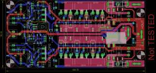
Valery, Jeff, Marc.... and any more was working out a 3OPS VFet Slewmaster Board, with same Output Power like 5OPS- Board is more compact- better
to fix in.
Marc makes a wonderful double layer Board- you can also build a Quasi OPS-
N-Channel- only change direction on Inverter, i think.
I like the quasi idea, so i collect it.
Look at Temperature Control- yellow circled.
Cheers Bangla.
Hallo.
Jason you remind me where i have read about.Work was done in the SlewMaster Build thread on using buffered verticals. Valery's and I found that adding a red LED in the emitter leg of the Vbe multiplier almost perfectly corrected the tempco of the bias spreader.
Valery, Jeff, Marc.... and any more was working out a 3OPS VFet Slewmaster Board, with same Output Power like 5OPS- Board is more compact- better
to fix in.
Marc makes a wonderful double layer Board- you can also build a Quasi OPS-
N-Channel- only change direction on Inverter, i think.
I like the quasi idea, so i collect it.
Look at Temperature Control- yellow circled.
Cheers Bangla.
Attachments
I was looking for a useful way to add an LED and I guess this could be it. Always good to have a visual indicator that amp is powered on.
It's going to take some work to set the resistor and pot for the Vbe - I always have a hard time with that - is there a method to calculate that?
It's going to take some work to set the resistor and pot for the Vbe - I always have a hard time with that - is there a method to calculate that?
Hallo.
Jason you remind me where i have read about.
Valery, Jeff, Marc.... and any more was working out a 3OPS VFet Slewmaster Board, with same Output Power like 5OPS- Board is more compact- better
to fix in.
Marc makes a wonderful double layer Board- you can also build a Quasi OPS-
N-Channel- only change direction on Inverter, i think.
I like the quasi idea, so i collect it.
Look at Temperature Control- yellow circled.
Cheers Bangla.
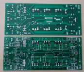
PCBway made from my gerber files nices board......2 Of them are partialy populated....
Marc
Attachments
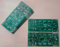
Those are nice boards. I have been using PCBWay lately too. Now if I can get someone to do a layout of this amp...
Those are nice boards. I have been using PCBWay lately too. Now if I can get someone to do a layout of this amp...
CFH7?
Yes. Prasi is busy so I am hoping Sonal can help out with this one. I just need to add the LED and figure out the new resistor values in the Vbe multiplier. And connect the protection diodes to the output.
yes,I was looking for a useful way to add an LED and I guess this could be it. Always good to have a visual indicator that amp is powered on.
It's going to take some work to set the resistor and pot for the Vbe - I always have a hard time with that - is there a method to calculate that?
It's a multiplier and the multiplier RATIO comes from the RATIO of the resistor ladder upper and lower.
Multiplier ratio = Rupper+Rlower/Rlower.
Bias voltage = Vbe*multiplier ratio.
Take an example.
Rupper=2k2
Rlower= 1kVR + 390r
Vbe=620mVbe
Max bias voltage = [{2k2+390}/390]*0.62 = 4.117Vbias
Min bias voltage = [{2k2+390+1k}/{390+1k}*0.62 = 1.601Vbias
Vbe will depend on the current density through the base emitter junction, on the area of that junction and on the temperature of that junction.
Using a sot23 will be different from a To92 and different again from a To126.
Even within package styles there will be differences.
Just to inform all of you, VSSA (Very Simple Symmetrical Amplifier) is my amp and it was sold in hundreds few years ago. Its successor is First One S which will be released this year. More in below VSSA link.
BTW Gaborbela is not electronic guy, he took sch from god knows where, so to be correct the original author of this topology is unknown.
I came to VSSA sch from my SSA and TSSA schematics from naturally developing the concept and did not know anything about the guy and his drawings. Just to be clear.
CFH7 Tempco
Hallo.
doing pcb routing like other good known here.
Very kind if you would work on a board.
I am happy to give a little tip here- if Andrew like the Tempco, it is good to
put it in?.
By reading i have recognize how difficult and complex it is to have all little
details in view.
The UNISlewMaster- Board is keep in mind- eventual a Quasi?
 Bangla
Hallo.
Marc nice that you looked over here. I know you are in same rangePCBway made from my gerber files nices board......2 Of them are partialy populated....
doing pcb routing like other good known here.
Very kind if you would work on a board.
I am happy to give a little tip here- if Andrew like the Tempco, it is good to
put it in?.
By reading i have recognize how difficult and complex it is to have all little
details in view.
The UNISlewMaster- Board is keep in mind- eventual a Quasi?
BanglaI have been using PCBWay lately too.
They do a nice job, but I don't care for the PayPal fee they charge which adds to the final cost.
I don't think PCB Shopper accounts for the fee when comparing prices.
yes,
It's a multiplier and the multiplier RATIO comes from the RATIO of the resistor ladder upper and lower.
Multiplier ratio = Rupper+Rlower/Rlower.
Bias voltage = Vbe*multiplier ratio.
Take an example.
Rupper=2k2
Rlower= 1kVR + 390r
Vbe=620mVbe
Max bias voltage = [{2k2+390}/390]*0.62 = 4.117Vbias
Min bias voltage = [{2k2+390+1k}/{390+1k}*0.62 = 1.601Vbias
Vbe will depend on the current density through the base emitter junction, on the area of that junction and on the temperature of that junction.
Using a sot23 will be different from a To92 and different again from a To126.
Even within package styles there will be differences.
For my case with 6k8 Rupper and 1k pot and 220R lower, what happens with LED?
- Home
- Amplifiers
- Solid State
- CFH7 Amp