I ran a simulation on the 3rd harmonic of a single EF output stage with different degeneration voltages across 0.1R emitter resistors. There is a very interesting H3 null at 10mV, and nothing seemed to be happening at 26mV. Someone posted the Oliver paper on the null point somewhere but I can't find it, though I'd like to see it.
here Barney Oliver: Class B Distortion in Audio Amplifiers
😎
The load impedance of a speaker varies considerabley over frequency, and we know that changing the load on an amp with moderate amounts of feedback will result in changes in distortion.
If the load goes from 16 Ohms (base port resonance for example) to 3 Ohms at 500~1kHz (bass speaker coil resistance dominated), thats a big difference, and if the feedback is moderate, the distortion will respond accordingly and go up at HF. Above say 5 or 10kHz, the impedance usually rises again, putting less of a load on the amp, so this again affects the overall distortion.
Nothing to do with interface modulation distortion or any of that stuff - just plain good old feedback stuff.
Self tried to mitigate these effects with his load invariant amp, and some of the designs on this forum with high loop gains are also pretty load invariant - so you will not see as big a change in distortion across frequency.
I should also point out, that in most cases, the loop gain of the amp decreases with frequency, so this should also be figured in as another factor contributing to the complex changes you see in distortion with a typical speaker load.
Bonsai
Then a situation where you have the highest (100%) feedback/error correction and trimmable output z to values even below zero around your OPS would not be so bad.
From all I see, it's not the feedback, but the resulting low Z output that deal with speaker induced nonlinearities.
Then a situation where you have the highest (100%) feedback/error correction and trimmable output z to values even below zero around your OPS would not be so bad.
From all I see, it's not the feedback, but the resulting low Z output that deal with speaker induced nonlinearities.
Is there an online reference where Self describes exactly what he means by "load invariant"? I'm seeing a bucket of worms and lots of potential miscommunication.
Oliver's paper basically seems to say "the linear region is 13mV-26mV degeneration". That's a lot of ground, and is not really the same as saying 26mV is the "null point". This makes sense though because the effect of degeneration on distortion is different depending on the load. For class A operation, I think 10mV is ideal because of the 3rd order harmonic null. In deep class AB, maybe higher bias is better, IF the harmonic profile is not adverse?
Oliver's paper basically seems to say "the linear region is 13mV-26mV degeneration". That's a lot of ground, and is not really the same as saying 26mV is the "null point". This makes sense though because the effect of degeneration on distortion is different depending on the load. For class A operation, I think 10mV is ideal because of the 3rd order harmonic null. In deep class AB, maybe higher bias is better, IF the harmonic profile is not adverse?
MiiB, Yes - I agree. You are attending to the problem in a different way
The lesson I take away from this is that you need to test amplifiers with real world loads. All this 1ppm b.s. into 8 ohm resistive load is nonsense - the load is much tougher than this.
Stereophile's JA tests amps with a simulated load and you can see the response wobble around (especially at HF). Thats a sure sign that you will have distortion arising from a non-linear load.
BTW, this is one of the reasons I like to design with lots of loop gain phase margin (60 degrees or more) and then I only have to use a small output inductor to provide capacitive load isolation - I've been using 0.6 to 1uH successfuly on my designs. I am not saying this will solve the problem, but a lower output Z helps as well.
Is there an online reference where Self describes exactly what he means by "load invariant"? I'm seeing a bucket of worms and lots of potential miscommunication.
Oliver's paper basically seems to say "the linear region is 13mV-26mV degeneration". That's a lot of ground, and is not really the same as saying 26mV is the "null point". This makes sense though because the effect of degeneration on distortion is different depending on the load. For class A operation, I think 10mV is ideal because of the 3rd order harmonic null. In deep class AB, maybe higher bias is better, IF the harmonic profile is not adverse?
Yes, thats the range BA quoted.
However, I just bias up my output stage so it runs nice 'n warm. A bit on 2nd and 3rd never hurt anyone 😉
"Null point"
Ahhh , someone noticed ! 😎
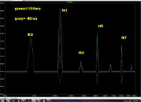
Stepping through biases from 100ma down to 20ma .... the "null" of
either H3/5/ or 7 occurs. Different "nulls" for each bias point - interesting.
40ma seems to be ideal (grey).
This does not happen in the same way with all amps. Topology
seems to be a factor.
(below) is this "effect" with my EF3/ CFA-X (vssa variant).
OS
Ahhh , someone noticed ! 😎
Stepping through biases from 100ma down to 20ma .... the "null" of
either H3/5/ or 7 occurs. Different "nulls" for each bias point - interesting.
40ma seems to be ideal (grey).
This does not happen in the same way with all amps. Topology
seems to be a factor.
(below) is this "effect" with my EF3/ CFA-X (vssa variant).
OS
Attachments
40ma seems to be ideal (grey).
This does not happen in the same way with all amps. Topology
seems to be a factor.
OS
An Amp I am screwing around with -- opt bias appears to be in the region of 60-80mA/device. The null is more narrow at 4 Ohms than at 8 Ohms.
Last night...outta here tomorrow morning for a 2-3 month diversion. I already took my vacation so I would be up for the Big One ! Long trip to third world countries. Its very interesting. Some one has to do it... might as well be me. Be talking at ya later when I can find an Internet connection. But I did get a mobile phone... if you can call it just a phone any more (Samsung Galaxy S 5. Hope it is as good as the hype says it is)
Thx - RNMarsh
If you plot the output stage gain vs bias current you get a very big difference in the curves (see Self for example and other plots done on this forum).
This is the main reason for the changes in harmonic strcuture vs bias current.
Also, explains why for example, HEC works so well - it flattens out the gain curve and suppresses the distortion components.
I suspect the topology dependence somes from the loop gain profile, OPS driving source impedance, and loading of the VAS.
40mA through 0.22R is about 9mV, so even lower than the 10mV point I got (giving degeneration voltage is the least vague way to identify different bias points in terms of transfer characteristic).
Anything preceeding the output stage that modifies the transfer characteristic can shift these points. The load-dependent harmonics may cancel and fight with the signal-dependent harmonics and this can result in wild harmonic behavior.
Of course, the varying Ft of the outputs with bias may be causing an audible phenomenon we mistakenly attribute to the harmonic profile. I've read things that suggest either could be the case. To exclude the Ft theory, I want to compare an output stage with 10mV/0.1R degeneration with one using 26mV/0.27R degeneration. Ft will be very close and the class A region just as wide, but the harmonic profile will be completely different, so this makes it an apt way to test what matters sonically in an output stage.
The best technical solution is to cure the problem where it is: Make your speaker's impedance flat from DC to 40KHz.best solution, to me, is to make sure that meaningful feedback is reducing the impact of the variable speaker load to the lowest level ...
It takes a RLC network to compensate the resonances of every speaker (with little coil diameter because the R) plus traditional Zobel to compensate the coil's inductances.. Usually R+(C+ R //(C+R)).
As it is parallel, you can easily compare instant with and without: The difference is obvious.
Have a nice trip and take care, Richard. And get back to us soon: we don't want to lose one of our 'Guru's ;-) too long.
Last edited:
Exactly my experience.The best technical solution is to cure the problem where it is: Make your speaker's impedance flat from DC to 40KHz.
It takes a RLC network to compensate the resonances of every speaker (with little coil diameter because the R) plus traditional Zobel to compensate the coil's inductances.. Usually R+(C+ R //(C+R)).
As it is parallel, you can easily compare instant with and without: The difference is obvious.
Distortion level, and distortion harmonics ratios change, and for the better.
IMHO, this is a must do to achieve proper sound, despite all the typical arguments that amp will take care of/ignore etc reactive loads.
Typical amplifiers are load dependant....load them with what looks like a 'clean' resistor and they will perform audibly better.
It's that simple.
Dan.
You will be sorely missed (in the interim).....it's time now for you to get up to speed with these modern pocket phone/internet gadget thingos 😉.Have a nice trip and take care, Richard. And get back to us soon: we don't want to lose one of our 'Guru's ;-) too long.
I have learned much from you.
Thank you.
Dan.
Last edited:
The best technical solution is to cure the problem where it is: Make your speaker's impedance flat from DC to 40KHz.
.......
As it is parallel, you can easily compare instant with and without: The difference is obvious.
Never even considered doing this. Thought that since I was running an active setup this wasn't necessary.
Another experiment to add to the list.
Jan.
Why is it such a big no no to divide the feedback into two loops..?? TMC or Cherry nested does that to a degree and get better results, I do it completely and get if not better, then at least more consistent results.
It's not a no-no, and if you're happy with it, just do it. It can also be a great learning tool.
But say that you have an amp, consisting of several stages, with a total gain Aol that differs from the required closed loop gain Acl by X dB.
Then we know that this X dB can be 'thrown away' in the form of nfb to make the amp more linear, wider bandwodth, lower Zout, more 'hifi', etc.
You can do that in several ways - you can divvy up the X dB into several nfb loops around some stages, in combination or not with a part as global nfb around the whole shebang.
But it has been proven that you get the maximum effect on the linearity etc. of the amp, the greatest improvedment, when all of X is used in a global feedback loop, and none around individual stages in whatever combination.
Now you are going to ask me for a reference, but I need some more time to find that...😱
Jan
Thank you for pointing this out. How do I miss these things?
Although, from sims I don't see the 5x reduction in THD with TMC vs TPC. I do see the benefit of the 2 pole nature of the TMC when comparing with single pole miller. TPC seems more effective but the square wave overshoot bothers me. The implementation of the rest of the amp must have significant effect.
The question in my head now is how the finer details of TMC compare to the "split" feedback method. Something to ponder me thinks...
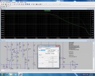
Here is example of how to have 2 pole response whithout the overshoot penalty.
Basically two shunts.
Attachments
One thing that puzzles me with amplifiers is why I get very different distortion results with loads, and with real speakers as loads the distortion is really bad. If feedback was the key to make load invariant amplifiers, then it would all be very easy. Frankly it's. not and I don't see feedback being the cure. Things are not so ideal as the theories tells us
I also address your previous posts as well as all the others that tend to state that (high) negative feedback circuits are unable to control reactive loudspeakers adequately.
At least, some can, have a look at the distortion numbers and figures with almost purely reactive loads at the end of this paper in french :
L'amplificateur de Mike Renardson à transistors Mosfet | A comme Audio
Due to its Mosfet output stage, this amplifier, conceived by Mike Renardson, has not a very low open output impedance. Its impressive specifications which are not disturbed at all by these loads qualified as "difficult" rely only on very high negative feedback.
I used those from decades. First, it simplify the design of passive filters as theoretical calculations will give practical results closer to the one expected. (Of course, you can simplify the whole network (filter + compensation) at the end to save components. Like always, passive filters need practical response curves measurements.Never even considered doing this. Thought that since I was running an active setup this wasn't necessary.
Another experiment to add to the list.
I used them in my active speaker's versions as well and i greatly encourage you to test-it and report your results 🙂.
Very audible difference, specially on kick drums and cymbals.
Last edited:
I used those from decades. First, it simplify the design of passive filters as theoretical calculations will give practical results closer to the one expected. (Of course, you can simplify the whole network (filter + compensation) at the end to save components. Like always, passive filters need practical response curves measurements.
I used them in my active speaker's versions as well and i greatly encourage you to test-it and report your results 🙂.
Very audible difference, specially on kick drums and cymbals.
You've convinced me. 🙂
I can see a logic behind this from a technical perspective, so it shall be done.
- Home
- Amplifiers
- Solid State
- CFA Topology Audio Amplifiers