It's not a no-no, and if you're happy with it, just do it. It can also be a great learning tool.
But say that you have an amp, consisting of several stages, with a total gain Aol that differs from the required closed loop gain Acl by X dB.
Then we know that this X dB can be 'thrown away' in the form of nfb to make the amp more linear, wider bandwodth, lower Zout, more 'hifi', etc.
You can do that in several ways - you can divvy up the X dB into several nfb loops around some stages, in combination or not with a part as global nfb around the whole shebang.
But it has been proven that you get the maximum effect on the linearity etc. of the amp, the greatest improvedment, when all of X is used in a global feedback loop, and none around individual stages in whatever combination.
Now you are going to ask me for a reference, but I need some more time to find that...😱
Jan
Jan, I would also be very interested in some references, just for better understanding of the reasons. This is a rather interesting point. We (almost) always use local NFBs in our designs (e.g. degeneration), almost in every stage, in order to maintain practically reasonable level of stability and balance (in some cases). So Aol is always a compromise. I know your point of view on this - keep it as high as possible and then apply a global NFB. But I'd like to "dive deeper" into this. I've got a feeling that in some cases deliberately arranged multiple NFB loops can improve the sonic qualities. Looking for more "theory" on this...
Cheers,
Valery
I'm searching, it's probably on my laptop with another million or so papers 😉
But note that 'improved sonic qualities' is not the same as better linearity, less distortion, more 'hifi' etc.
I would never state that increased feedback leads to improved sonic qualities - there's at best a very weak link between the two.
Sonic qualities are very personal and one can prefer the sonic qualities of a certain amplifier over another one that may be more 'hifi' in the literal sense.
Jan
'improved sonic qualities' means more transparent, less 'signature' in my spirit.But note that 'improved sonic qualities' is not the same as better linearity, less distortion, more 'hifi' etc.
Because the way we measure (on continuous sin or square signals most of the time) we are far from musical signals, made of transients. And the way our ears+brain discriminate.
No other way to explain why two amplifiers, with similar measurements (very low HD) can sound so different for most of us.
40mA through 0.22R is about 9mV, so even lower than the 10mV point I got (giving degeneration voltage is the least vague way to identify different bias points in terms of transfer characteristic).
Anything preceeding the output stage that modifies the transfer characteristic can shift these points. The load-dependent harmonics may cancel and fight with the signal-dependent harmonics and this can result in wild harmonic behavior.
Of course, the varying Ft of the outputs with bias may be causing an audible phenomenon we mistakenly attribute to the harmonic profile. I've read things that suggest either could be the case. To exclude the Ft theory, I want to compare an output stage with 10mV/0.1R degeneration with one using 26mV/0.27R degeneration. Ft will be very close and the class A region just as wide, but the harmonic profile will be completely different, so this makes it an apt way to test what matters sonically in an output stage.
Very usefull study

Just a quick query, is the results obtained pertaining to reduced total level of THD or the reduction of just certain harmonics which some deem as harmfull.
Christophe,
When you are adding your conjugate network are you actually adding two conjugate networks in parallel at the speaker terminals? One to take care of the normal impedance rise over frequency from low to high and a second network to take care of the fs resonant impedance at speaker resonance? I know some only take care of the overall impedance rise and ignore the resonant frequency where they tune the bass reflex and others take care of both.
When you are adding your conjugate network are you actually adding two conjugate networks in parallel at the speaker terminals? One to take care of the normal impedance rise over frequency from low to high and a second network to take care of the fs resonant impedance at speaker resonance? I know some only take care of the overall impedance rise and ignore the resonant frequency where they tune the bass reflex and others take care of both.
An Amp I am screwing around with -- opt bias appears to be in the region of 60-80mA/device. The null is more narrow at 4 Ohms than at 8 Ohms.
Last night...outta here tomorrow morning for a 2-3 month diversion. I already took my vacation so I would be up for the Big One ! Long trip to third world countries. Its very interesting. Some one has to do it... might as well be me. Be talking at ya later when I can find an Internet connection. But I did get a mobile phone... if you can call it just a phone any more (Samsung Galaxy S 5. Hope it is as good as the hype says it is)
Thx - RNMarsh
The phone is as good as the hype but it will still drive you nuts.
Cristophe/Kindhornman.. you can correct speakers to eternity, reason is the the impedance issues varies quite a bit with the SPL. So what is right at one level, messes the hole deal up at another level. Better to work the issues at a driver level. It quite possible to reduce VC inductance to very little and also to improve motor linearity by a lot of different means. The most radical i have done is to make a driven magnet structure where you simply drive a counter inductance around the pole-piece. then you driver can be 100% flat in the impedance curve. While it measured good, it did not do anything good for the sound..🙁 Now this here is a CFA thread) so the point is that we must live with the obstacles presented to us form the speaker side. not two speaker are the same. so the flexibility and load tolerance must be on the amplifier side.
'improved sonic qualities' means more transparent, less 'signature' in my spirit.
.... yes... 'Improved' is more towards the sound of real instruments playing. I only get this when the amps are more linear and less distortion of any kind. More transparent.
Heading for the airport in 30 minutes. Will miss you guys (for awhile). I'll have max fun in your place. 🙂
-RNM
Last edited:
.... yes... 'Improved' is more towards the sound of real instruments playing. I only get this when the amps are more linear and less distortion of any kind. More transparent.
-RNM
I understand that this is what it means to you, and it is also what it means to me.
However, in my humble experience, if you ask four people you get five different answers, hence my reluctance.
As an example, se tube aficionados by definition do not agree with that.
Have a good trip Richard, come back in one piece ! 😉
jan
Have fun Richard. I expect that this is more than just a fun excursion, checking on both your new condo and also your manufacturing facility I imagine. Eat some fun things and tell us about it, a db taste test would be interesting!
MiiB,
Personally I think it is incumbent that the designer of any raw frame driver give this type of conjugate network information away with the speaker or add it to the raw frame driver as a part of the driver attached at the terminals or as a small separate board to be added by the end user. This would go a long way to correcting the problems with various speaker loadings on amplifiers and correct many problems we now see with loudspeakers. I do all I can to improve the speaker itself physically during the design but this can only go so far and then you need to correct any other impedance rise with a conjugate circuit. No reason to handicap any amplifier with these problems, that is asking to much of every amplifier to put up with this issue that does have a solution. I am with Christophe and many others on this subject.
Personally I think it is incumbent that the designer of any raw frame driver give this type of conjugate network information away with the speaker or add it to the raw frame driver as a part of the driver attached at the terminals or as a small separate board to be added by the end user. This would go a long way to correcting the problems with various speaker loadings on amplifiers and correct many problems we now see with loudspeakers. I do all I can to improve the speaker itself physically during the design but this can only go so far and then you need to correct any other impedance rise with a conjugate circuit. No reason to handicap any amplifier with these problems, that is asking to much of every amplifier to put up with this issue that does have a solution. I am with Christophe and many others on this subject.
A test I've not yet seen undertaken.
Let's have two mono amps of standard quality (low output impedance required) and the most identical as possible.
Feed them with exactly the same signals.
Set the output levels very precisely and with a sufficient margin such as no amp will be overloaded or current limited during the test.
Load the first amp with a purely resistive load and the second one by a loudspeaker or any other representative reactive load.
Play some music or arbitrary signals while recording the two output voltages.
Analyze the record at will, beginning of course by a subtraction.
Will there be objectively observable differences between the outputs ?
If so, what are they ? and from which origin ?
PS
While proposing this test, I'am thinking of those made in the seventies by Baxandall and Hafler and which are still valid.
Kindhorman.. for the High Frequency driver I solely work with a sealed Ribbon-tweeter the impedance of that is pure ohmic with no resonances what so ever. For the base driver you see two typical issues. One is the impedance rise due to the VC inductance., this issue is actually aiding the cross over as it is in series with the inductance you typically use to shape the upper frequency roll-of for the base driver. the other issue is largely dependent on how the driver is used in the cabinet. Volume flow resistance and SPL all plays a significant role in how and where this resonance based impedance "peak" is placed and what the magnitude of it is. As this is application dependent, The driver manufacturer just can't build any universal correction circuit for that. To my experience any parallel circuit aiming to reduce this impedance bump, degrade the speaker performance, as it robs the amplifier any means of control, by providing a current escape path, I have also seen resonances occur in the LCR based suction circuits. They are NOT a part of my speaker designs. I work on other levels to minimise these dynamic unlinearities, mostly with acoustic flow and mechanical related corrections.
Point is that the amplifier must deal with these issues, by having low output-impedance and sufficient PSU storage headroom.
Point is that the amplifier must deal with these issues, by having low output-impedance and sufficient PSU storage headroom.
Last edited:
Linearising the impedance of loudspeakers has the effect that the output seen by the amplifier is lowered, then, for the same voltage output, it has to deliver more current. As the greatest non-linearities of an amplifier come from the current variations in the output stage, a loudspeaker having its impedance made resistive will make the distortion of the system higher (some apparently prefer). That was a lesson by Douglas Self a long time ago.
EDIT
Linearising a driver impedance may help to design a passive crossover.
But there is no justification to linearise a whole loudspeaker.
With electrodynamic drivers, amplifiers have more chances to meet more problems with low impedance loads than with reactive loads.
EDIT
Linearising a driver impedance may help to design a passive crossover.
But there is no justification to linearise a whole loudspeaker.
With electrodynamic drivers, amplifiers have more chances to meet more problems with low impedance loads than with reactive loads.
Last edited:
lots of dubious statements lately - was going better a few pages back
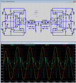
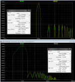
for a simmed look at the Z load issue I went back to my Cordell MOSFET amp sim http://www.diyaudio.com/forums/solid-state/240712-cfa-topology-audio-amplifiers-558.html#post3878856 - which already tests output injected current effects
copied the whole amp, loaded with 4 Ohm R one copy (outr), 2 Ohm series with 50u/5uF cap on the outz copy of my simplified Bob's MOSFET EC amp, running at 1 kHz (50u), and again at 10 kHz (5u) for nearly the same Iout, just phase shifted
the summary - sim again supports Cherry and Cordell - the distortion with a out of phase (or output injected) current is the same order of magnitude as the distortion of the amp putting out the same current in a resistor load
this is a consequence of the usual situation that output stage "current gain" varying over the operating region is the major error in most audio power amps, with follower "100% V feedback" mostly linearizing the V gain
by running at both 1 and 10 kHz we can see the ~10:1 increase in error components in the fft with Bob's compensation
Attachments
Last edited:
I have done this as a DBLT. Absolute Listening Tests - Further ProgressLet's have two mono amps of standard quality (low output impedance required) and the most identical as possible.
Feed them with exactly the same signals.
Set the output levels very precisely and with a sufficient margin such as no amp will be overloaded or current limited during the test.
Load the first amp with a purely resistive load and the second one by a loudspeaker or any other representative reactive load.
Play some music or arbitrary signals while recording the two output voltages.
Analyze the record at will, beginning of course by a subtraction.
Will there be objectively observable differences between the outputs ?
If so, what are they ? and from which origin ?
PS
While proposing this test, I'am thinking of those made in the seventies by Baxandall and Hafler and which are still valid.
If you use good amps like Baxandall & Hafler designs, the differences will be due to the different Zo .. mainly the output L. You can easilly tell different speaker cables in this test.
But if you use Golden Pinnae amps, you will find that many are marginally stable into real speakers.
_____________
I'm really a speaker man but disagree with Kindhornman. I insist that amps be able to handle the evil loads I dream up. Mwaah haa ha ha! 😀
On a more serious note, I worked for KEF who did this on several commercial speakers in the 90s. They found no benefit except for some Golden Pinnae amps .. but those were not good amps.
The speakers had to be designated nominal 4R instead of 8R
It seem obvious than simpler is the error signal, better it is
An interesting statement. Let's precise :
the higher is the open loop gain (avoiding local feedback by degenerative emitter resistors), the smaller the error signal is. And then the simpler it is.
I really love the ones (always the same 3, in my ignore list who refer endlessly to books, papers or simulations) who never try to understand and experiment anything out of their habits *in real world* before contradicting for the pure pleasure.
I propose them to experiment what i call "motional compensation" for real, on their speakers, making a comparison of acoustic response curves. (yes they need some measuring instruments, like Bruel & Kjaer mic)
(of course, they will never do-it 🙂
They will see the obvious difference, and it is only one of the measurements we made in the 80s. plus waterfalls, step response etc.
Oh, can-we believe source impedance is not so negligible after a speaker cable and worse after serial resistances in a low pass filter ?
Oh, can they understand what happens with phase and damping (even when you hit your bass speaker membrane( unplugged) the sound is very different with this network and without ) ?
I'm really sorry if they are exhausted by things i had experienced and that works.
Yes there is a difference, with benefits on several enclosures, noticed by hundred of customers in direct comparisons at the 'Maison du haut parleur' with the enclosures designed by Mr Delamare, who used this kind of compensation.
Last, it is funny to read the same guys arguing about 0.0001% of distortion, when you can measure more than 1db impact in the response curve !!!!!!
Boring !
Linear impedance.
I can make crossovers that have linear impedance without a load matching network that fryes power.
I can make crossovers that have linear impedance without a load matching network that fryes power.
- Home
- Amplifiers
- Solid State
- CFA Topology Audio Amplifiers