One thing that puzzles me with amplifiers is why I get very different distortion results with loads, and with real speakers as loads the distortion is really bad. If feedback was the key to make load invariant amplifiers, then it would all be very easy. Frankly it's. not and I don't see feedback being the cure. Things are not so ideal as the theories tells us
Anybody ever told you something was ideal? Was it a car salesman, perhaps?
Anybody worth his salt in audio knows feedback isn't ideal.
It's like what they say about democracy: it's the worst system of government, except for all the other systems 😉
Edit: Your claim that feedback doesnot correct errors that originate from outside the loop is provable wrong. Your counterclaim for 'idealism' does not exist.
Jan
Last edited:
MiiB,
One of the things you should be aware of as a fellow speaker designer is that the load impedance of most speakers is far from ideal. Many speakers are not a pure impedance load, but can be highly reactive and or capacitive as in an electrostatic panel. If you are not doing some form of passive impedance correction this is something you should really be investigating, a conjugate network can do wonders and I would bet you money that this will change your thinking on the feedback to the amplifier from the speakers.
One of the things you should be aware of as a fellow speaker designer is that the load impedance of most speakers is far from ideal. Many speakers are not a pure impedance load, but can be highly reactive and or capacitive as in an electrostatic panel. If you are not doing some form of passive impedance correction this is something you should really be investigating, a conjugate network can do wonders and I would bet you money that this will change your thinking on the feedback to the amplifier from the speakers.
Jan.
Why is it such a big no no to divide the feedback into two loops..?? TMC or Cherry nested does that to a degree and get better results, I do it completely and get if not better, then at least more consistent results.
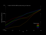
Off course the amplifier is capable of correcting the voltage errors from the outside as they to will be present at the output node. but what about out of phase currents..??When I measure my speaker driver I sometimes also measure the distortion from the amplifier. I have a pretty good impression on the performance driving pure resistive loads, like 3, 5, 8 ohms, then when I measure a driver, I also measure the amplifier distortions as to get a clearer picture of my driver performance. There I see that the amplifier distortion climbs with the reactive load. even if the load never goes below 5.6 ohms. Why is that if the feedback is able to correct it..??
Kind Hornman, These speaker impedance correction circuits does (to my experience) come with a sonic penalty, most of the issues they deal with are mechanical induced resonances, At that is the place i try to work first and foremost.
Why is it such a big no no to divide the feedback into two loops..?? TMC or Cherry nested does that to a degree and get better results, I do it completely and get if not better, then at least more consistent results.
Off course the amplifier is capable of correcting the voltage errors from the outside as they to will be present at the output node. but what about out of phase currents..??When I measure my speaker driver I sometimes also measure the distortion from the amplifier. I have a pretty good impression on the performance driving pure resistive loads, like 3, 5, 8 ohms, then when I measure a driver, I also measure the amplifier distortions as to get a clearer picture of my driver performance. There I see that the amplifier distortion climbs with the reactive load. even if the load never goes below 5.6 ohms. Why is that if the feedback is able to correct it..??
Kind Hornman, These speaker impedance correction circuits does (to my experience) come with a sonic penalty, most of the issues they deal with are mechanical induced resonances, At that is the place i try to work first and foremost.
"TMC" is a 2-pole technique - with some adjustment of part values the loop gain can be identical to 2-pole with the R to ac gnd when TMC is measured "inside" the loop formed by the bootstrap R, measuring the loop gain seen by the output stage - which is what matters for stability
and I recall that a long expired US patent was eventually found
and there's Baxandall: http://www.douglas-self.com/ampins/baxandall/Baxandall papers 34.jpg
Yes, they are both TPC, and we could again get into another long discussion on the equivalence or not if the two. 🙂
Interface Intermodulation Distortion was another rerun of someone trying to make a name as a audio guru - and failing undergrad feedback theory
this played out a few times in the pages of the Audio Engineering Society Journal - principally 1970s-80s
Cordell did the conventional math and the experimental measurement http://www.cordellaudio.com/papers/interface_intermodulation_distortion.pdf
Cherry as well in JAES at the same time
there's considerable distance between "conventional engineering doesn't know everything" and most of what is put forth as feedback amplifier "problems" in this thread
Bob's paper, book, Cherry detail the tug-of-war test - put an amp at each end of a power R load, put any combination of signals/varying phase/frequency into each side - which then drags the output stage I,V over however much you want to design the amp for, test for
one end's signal could be harmonics of the other side's "fundamental" - very clean test to do - no earmuffs needed
still have to understand measurement, ground loops, common impedance coupling, feedback takeoff, measurement test "point"/reference, all of the usual - then your results should be just as boring as the conventional EE theory says - if not, then really wring out your measurements, amp's before writing new papers for publication
Last edited:
MiiB,
I am not talking about notch filters and resonance fixes, just impedance correction due to the rising rate of the voicecoil in the gap. I use a Faraday sleeve in my motor design and very linear motor designs so I don't see any strange things but you will still see some impedance rise with frequency. This is what I propose that should be considered with the conjugate network.
I am not talking about notch filters and resonance fixes, just impedance correction due to the rising rate of the voicecoil in the gap. I use a Faraday sleeve in my motor design and very linear motor designs so I don't see any strange things but you will still see some impedance rise with frequency. This is what I propose that should be considered with the conjugate network.
One thing that puzzles me with amplifiers is why I get very different distortion results with loads, and with real speakers as loads the distortion is really bad. If feedback was the key to make load invariant amplifiers, then it would all be very easy. Frankly it's. not and I don't see feedback being to cure. Things are not so ideal as the theories tells us
Total. 31650
Hello MiiB,
Could you show a schematic of what you mean. Are you saying when you place a " speaker as the load" of you amplifier that the that when your measure the THD of the voltage developed across the amplifier speaker terminals that you get different THD when you change the speaker.
A number of reasons - practical feedback starts to fail in its ability to correct in the area where it is most needed, at high frequencies; and it is badly affected by power supply misbehaviour, something which is usually completely ignored. One solution which I use is to make sure that the simulated circuitry behaves itself, in every part of it, at 200kHz, then you should be right at 20kHz ...One thing that puzzles me with amplifiers is why I get very different distortion results with loads, and with real speakers as loads the distortion is really bad. If feedback was the key to make load invariant amplifiers, then it would all be very easy. Frankly it's. not and I don't see feedback being to cure. Things are not so ideal as the theories tells us
Total. 31650
Feedback should do its job, in all practical uses of the amplfier ...
There is a very simple explanation of this. Moving coil Speaker impedance is highly non-linear.One thing that puzzles me with amplifiers is why I get very different distortion results with loads, and with real speakers as loads the distortion is really bad. If feedback was the key to make load invariant amplifiers, then it would all be very easy. Frankly it's. not and I don't see feedback being to cure. Things are not so ideal as the theories tells us
If the Power Amp has ANY output Z, this will result in more THD. Even the usual output inductor in a power amp is sufficient to make this result in worse THD for a speaker compared to a 8R resistor.
This effect is MUCH greater than that due to amps not liking reactive loads .. though many Golden Pinnae amps are much more affected by reactive load (in)stability.
Can you give us some figures of what you measured and how you did it? ie what amp, what speaker, level, frequency, instrument etc.
Then can you measure the Output Z of the amp .. preferably at different current levels .. as jcx and others have recommended?
I ran a simulation on the 3rd harmonic of a single EF output stage with different degeneration voltages across 0.1R emitter resistors. There is a very interesting H3 null at 10mV, and nothing seemed to be happening at 26mV. Someone posted the Oliver paper on the null point somewhere but I can't find it, though I'd like to see it.
Attachments
Ideal feedback will reduce that Output Z to negligible levels, at all frequencies of interest - so the best solution, to me, is to make sure that meaningful feedback is reducing the impact of the variable speaker load to the lowest level ...If the Power Amp has ANY output Z, this will result in more THD. Even the usual output inductor in a power amp is sufficient to make this result in worse THD for a speaker compared to a 8R resistor.
Okay, but are the harmonics appearing across the source impedance to the speaker adding to or subtracting from the harmonics the speaker is actually producing?
Last edited:
Adding, if you mean the speaker harmonics being those created by the cone movement not being linear in its coupling to the air - I would like the voice coil to see a perfect voltage source across it, ideal damping, in its frequency range - probably why active speakers setups can be very impressive ...
At different frequency ranges a speaker may favor current drive or voltage drive in terms of distortion. This is because the low source impedance may short back-EMF signals which would otherwise keep the speaker linear. In this case, the harmonics across the source impedance actually subtract from the harmonics the speaker normally produces. This is true for any device which is more linear with a high impedance source.
For this reason I doubt that simply lowering the source impedance will improve much. The problem needs an informed analysis.
For this reason I doubt that simply lowering the source impedance will improve much. The problem needs an informed analysis.
Non est tantum facile.At different frequency ranges a speaker may favor current drive or voltage drive in terms of distortion. This is because the low source impedance may short back-EMF signals which would otherwise keep the speaker linear. In this case, the harmonics across the source impedance actually subtract from the harmonics the speaker normally produces. This is true for any device which is more linear with a high impedance source.
For this reason I doubt that simply lowering the source impedance will improve much. The problem needs an informed analysis.
This is a very complex issue. Both current drive HiZ and -ve Output Z result in less speaker distortion. There's a separate thread on this subject. But its the total distortion of amp + speaker that's reduced
_______________
To explain MiiB's observation .. measured THD at the amp terminals with a real speaker is always more THD than an 8R resistor.
You can test/check this easily.
To demonstrate evil Output Z, you need to check that your amp is stable on your speaker without it's output L. Many Golden Pinnae amps including some designed by famous names on this forum are not. Their poorer THD on real speakers is symptomatic of marginal instability.
If it is stable. you take out the output L and measure THD with speaker connected again.
And don't forget to measure the Output Z, with and without output L, with frequency like jcx suggested.
Has anyone studied this rigorously - available to read online? In particular, in the frequency range that the speaker was designed to operate in?At different frequency ranges a speaker may favor current drive or voltage drive in terms of distortion.
Here's one of the few online references I know of. I haven't found a more detailed explanation:
Current-Drive - The Natural Way of Loudspeaker Operation
Current-Drive - The Natural Way of Loudspeaker Operation
- Home
- Amplifiers
- Solid State
- CFA Topology Audio Amplifiers